Home
Vertiv
Power Supply
NetSure 7100 Series
Vertiv NetSure 7100 Series Installation Manual
5
of 1
of 1 rating
222 pages
Give review
Manual
Specs
To Next Page
To Next Page
To Previous Page
To Previous Page
Loading...
Vertiv
|
NetSure
7
100
Series
-
48V DC Po
wer System
Installation
Manual (
IM
582127000
)
|
Rev. BB
40
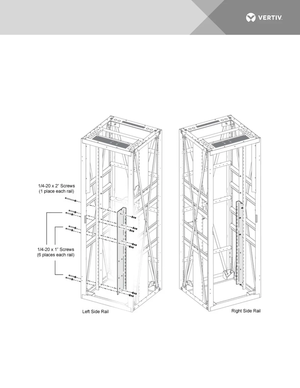
Figure
17
:
Installin
g
a
Battery Tray Mounting
Kit P/N
565004
(cont’d on next pa
ge)
1
.
Remove
the
twelve
(12)
1/4-20
x
3/4”
screws,
locations
shown.
Save
washers
and
nuts
for
reassembly
.
2.
Remove
the
two
(2)
1/4-20
x
1.75”
screw
,
locations
shown.
Save
washers,
spacers,
and
nuts
for
reassembly
.
3.
Assemble
battery
tray
mounting
kit
rails
in
location
shown.
39
41
Table of Contents
Default Chapter
3
Table of Contents
3
Admonishments Used in this Document
6
Important Safety Instructions
7
Safety Admonishments Definitions
7
General Safety
7
Voltages
7
AC Input Voltages
7
DC Input Voltages
7
DC Output and Battery Voltages
8
Battery
8
Personal Protective Equipment (PPE)
9
Hazardous Voltage
9
Handling Equipment Containing Static Sensitive Components
10
Maintenance and Replacement Procedures
10
Static Warning
11
Customer Documentation Package
13
Installation Acceptance Checklist
14
Installing the System
16
General Requirements
16
Procedures When the System Is Installed in an Enclosure
17
Removing the Enclosure Rear Panels
17
Removing the Enclosure Side Panels
17
AC Input Conduit Options
17
Reversing the Enclosure Front Door
18
Placing and Securing the Relay Rack(S) to the Floor (if Applicable)
20
Placing the Enclosures, Bolting Enclosures Together, and Securing the Enclosure(S) to the Floor (if Applicable)
24
Mounting the Distribution Cabinet with Module Mounting
30
Assembly(S)
30
Installing a 582127000 List 93 Battery Tray
34
Only)
34
Installing a Battery Tray
34
Installing Optional Battery Disconnect Circuit Breakers
35
Installing Optional Anderson Battery Connector Kit
36
Installing Optional Front Battery Cover
37
Installing Optional Circuit Breaker Guard
38
Installing a Battery Tray Mounting Kit, P/N 565004
39
Installation Only)
39
Removing the Enclosure Rear and Side Panels
39
Installing the List 93 Battery Tray
43
Installing the Enclosure Rear and Side Panels
43
Installing Optional Battery Busbar Extension Kit, Part No. 562364
44
Installing Optional Battery Busbar Extension Kit, Part No. 554541
46
Installing Optional Lug Adapter Busbar Kits, Part Nos. 534449 and
48
Installing Optional Lug Adapter Busbar Kit, Part No. 562888
50
Installing Circuit Breakers and Fuses
52
Setting Jumpers and Switch Options
66
Circuit Card Locations
66
Jumpers on System Interface Circuit Card (Main Bay Only)
68
Switch Settings on IB2 Interface Board (Main Bay Only)
69
Switch Setting on Optional EIB Interface Board (Main Bay Only)
70
Switch Setting on SM-DU (Supplemental Bays Only)
73
Switch Setting on SM-DU
77
Making Electrical Connections
79
Important Safety Instructions
79
Wiring Considerations
79
Relay Rack or Enclosure Grounding Connection (Frame Ground)
80
Central Office Ground Connection
80
Nominal 208 VAC, 240 VAC, 277 VAC, or 277 VAC / 480 VAC Input and Equipment Grounding Connections (if Equipped)
82
Volts DC Input and Equipment Grounding Connections
114
Equipped)
114
External Alarm, Reference, Monitoring, and Control Connections
123
Circuit Card Locations
123
System Interface Circuit Card
125
IB2 (Controller Interface Board) Connections (if Required)
127
Only)
127
Optional EIB (Controller Extended Interface Board) Connections
132
Required) (Main Bay Only)
132
Optional SM-DU+ and Shunt Interface Board
138
Connecting a Device or System to the Controller's CAN Bus
140
Controller Ethernet Connection (if Required)
141
Bay-To-Bay Communications Cable Connections
145
Installing Bay-To-Bay Busbars (582127000 List 1 with List 2 / List 3) (for System Mounted in a Relay Rack)
148
Installing Bay-To-Bay Busbars (582127000 List 1 with List 7 / List 8) (for System Mounted in an Enclosure)
150
Control Bus Connections between Controller and Module Mounting Assemblies Spec. No. 588705000 and 588705500
153
Control Bus Connections between Controller and Module Mounting Assemblies Spec. No. 588705300
155
Control Bus Connections between Controller and Module Mounting Assemblies Spec. No. 588705400
157
Connecting Converter Output Cables 582127000 List 60
159
Load Connections
162
Recommended Torques
162
Load Connections to Single Voltage Distribution Panels
163
Load Connections to Dual Voltage Distribution Panels
168
Load Connections to Return Bar
173
Load Connections to Bulk Output Panel
173
Load Connections to GMT Distribution Fuse Block
174
Battery Connections
175
Important Safety Instructions
175
Recommended Torques
175
Battery Connections to Optional Battery Disconnect Distribution
175
Panels
175
Battery Connections to Distribution Cabinet Battery Busbars (for System Mounted in a Relay Rack or Enclosure)
179
Battery Connections to Bay-To-Bay Rectifier Busbars (582127000 List 1 with List 2 / List 3) (for System Mounted in a Relay Rack)
182
Battery Connections to Optional Battery Busbar Extension Kit P/N 562364 (for System Mounted in a Relay Rack or Enclosure)
183
Battery Connections to Optional Battery Busbar Extension Kit P/N 554541 (for System Mounted in an Enclosure)
185
Battery Connections to Optional Battery Landing Busbar Kit P/N 553584 (for System Mounted in a Relay Rack)
186
Battery Connections to Optional Battery Landing Busbar Kit P/N 555478 (for System Mounted in a Relay Rack)
187
Installing and Connecting Batteries in List 93 Battery Tray (if Furnished) (for System Mounted in a Relay Rack)
188
Installing the Modules
197
Installing Rectifier or Converter Modules into Spec. No. 588705000 Module Mounting Assemblies
197
Installing Rectifier Modules into Spec. No. 588705500 Module
199
Mounting Assemblies
201
Installing the Rectifier and Converter Modules into Spec. no
201
588705300 Module Mounting Assemblies
201
Installing Rectifier Modules into Spec. No. 588705400 Module
203
Mounting Assemblies
203
Initially Starting, Configuring, and Checking System Operation
205
Initial Startup Preparation
205
Initially Starting the System
205
ACU+ Controller Procedure
205
NCU Controller Procedure
213
Checking System Status
219
Final Steps
220
Other manuals for Vertiv NetSure 7100 Series
Quick Start Guide
130 pages
User Manual
106 pages
Installation And User Manual
22 pages
5
Based on 1 rating
Ask a question
Give review
Questions and Answers:
Need help?
Do you have a question about the Vertiv NetSure 7100 Series and is the answer not in the manual?
Ask a question
Vertiv NetSure 7100 Series Specifications
General
Brand
Vertiv
Model
NetSure 7100 Series
Category
Power Supply
Language
English
Related product manuals
Vertiv NetSure 731 A91
40 pages
Vertiv NetSure 801 AG1
76 pages
Vertiv NetSure 531 A91
40 pages
Vertiv NetSure V200E50
36 pages
Vertiv NetSure R48-3000e3
22 pages
Vertiv NetSure 5100 Series
80 pages
Vertiv NetSure 2100 Series
24 pages
Vertiv NetSure 8200 Series
56 pages
Vertiv ALPHA 1800
4 pages
Vertiv Liebert APM 400
97 pages

 Loading...


