Chapter 5: Detailed description of parameters
139
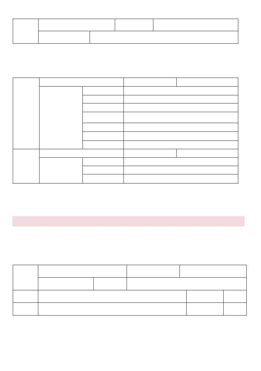
These parameters are used to set the delay time of the inverter when the terminal status
is changed.
At present only FWD, REV and S1 support the delay function.
Selecting the allowed S-mode 1
REV allowed mode (0-1, the same as FWD)
S1 allowed mode (0-1, the same as FWD)
S2 allowed mode (0-1, the same as FWD)
S3 allowed mode (0-1, the same as FWD)
Selecting the allowed S-mode 2
These parameters are used to set the digital input terminal mode. Terminal S is enabled
when connected to GND and blocked when disconnected from GND.
Group P6: Output Terminals
V 800 includes 1 standard multifunction analogue output connector FOV, 1 multifunction
output relay output and M01 terminal (used for high-speed pulse output or open collector
output).
M01 Functions (output - open collector OC)
Relay output function (RA-RB-RC)
These two parameters are used to select the functions of the five digital output terminals.
RA-RB-RC are the relevant relay on the control board and on the add-on card. The output
terminal functions are described in the following table.