June 11, 2015, 715004754 Rev. A
Page 27
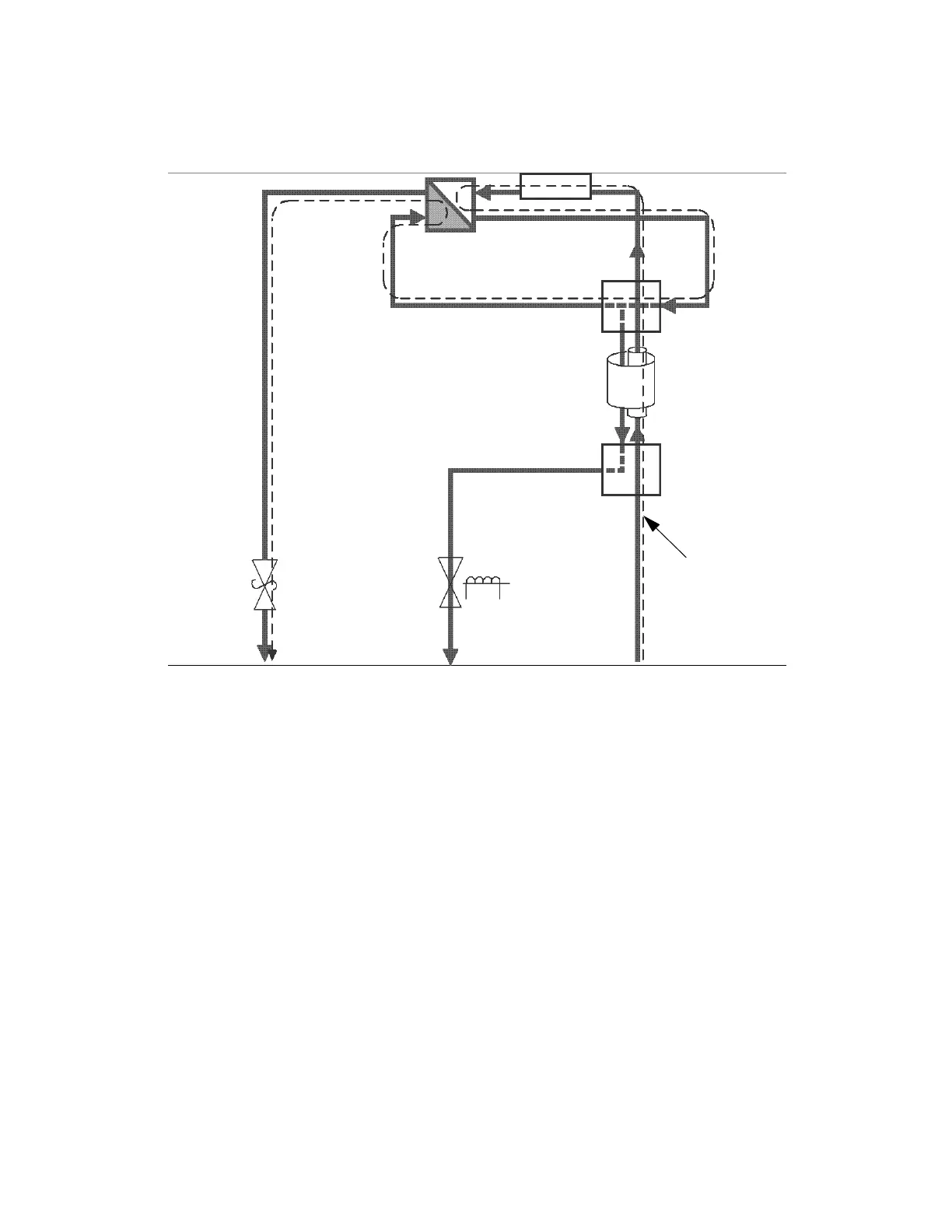
Figure 1–7: Flow path during purge
You purge the flow cell before an analysis to pass fresh mobile phase into the
reference side of the cell. Therefore, no chromatographically significant data is
available during a purge.
An icon in the front panel display and remote interface indicates when the detector is
engaged in purge mode.
You specify a purge from the front panel by pressing the Purge key. Doing so toggles
the purge state, unless it is overridden by the purge input signal. You can also specify
a purge from the rear panel; from a remote interface; or via the data system, where
you can define a duration.
1.3.4.2 Recycle mode
You engage the recycle mode via the detector’s front panel, or remote control
interface like a data system or controller. A programmatically controlled recycle
(solenoid) valve diverts the outlet fluid to one of two ports. An icon appearing in the
front panel display indicates when the unit is in recycle mode. The ports of the recycle
valve and their corresponding outlet lines are labeled accordingly.
An external recycling event input can engage the detector's recycle mode on each
transition, according to how the event is configured. You can also disable the input.
Relief
valve
(opened)
Fluid path for
purge mode
Solenoid
valve
(closed)
Flow cell
End Cap HE
Reference
Sample
Cross section
Counter
current HE
Sample In
Waste out
Purge out
Tee connection