June 11, 2015, 715004754 Rev. A
Page 28
1.3.5 Fluid path components
The fluid path of the 2414 RI detector includes these components:
• Countercurrent heat exchanger
• End-cap heat exchanger
• Flow cell, with sample and reference sides
• Solenoid valve
• Pressure relief valve
• Recycle valve
• Inlet and outlet tubing
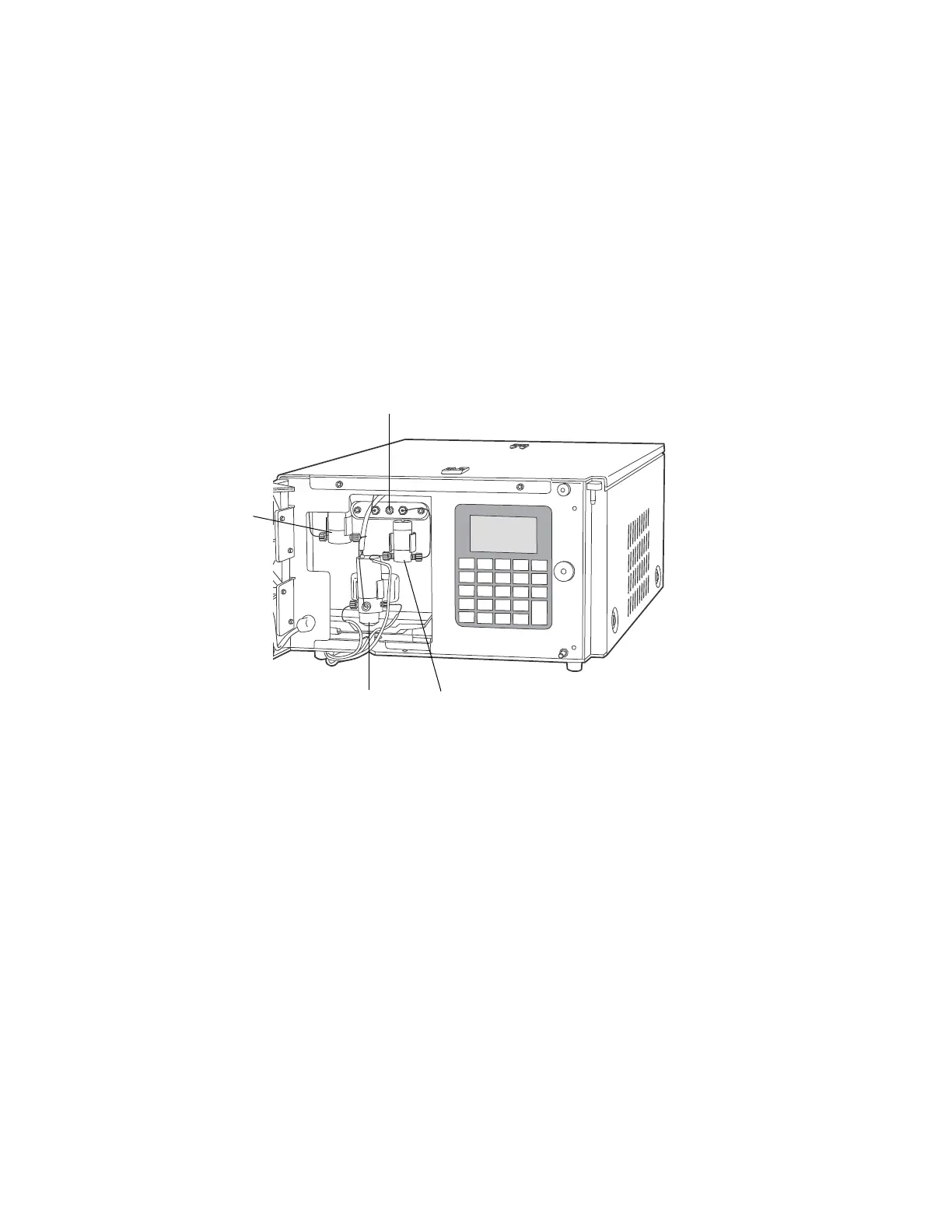
Figure 1–8: 2414 RI detector external plumbing and valves
1.3.5.1 Countercurrent heat exchanger
The countercurrent heat exchanger minimizes temperature fluctuations in the sample
stream. The device’s sample inlet and outlet lines are coaxial, which facilitates heat
exchange between incoming and outgoing fluids.
1.3.5.2 Flow cell
The flow cell consists of two fused, quartz, hollow prisms. Each cell has an inlet and
outlet. One of the prisms constitutes the cell’s sample side through which a constant
flow of eluent passes during analysis.
The other prism constitutes the cell’s reference side. It is filled with fresh solvent
when you purge the detector during equilibration. When you switch from purge to
normal operation, the solenoid valve opens, and the pressure relief valve shuts,
stopping the flow of solvent through the reference prism but leaving the cell filled with
solvent.
Solenoid
purge valve
Inlet line
Recycle
valve
Pressure
relief valve