June 11, 2015, 715004754 Rev. A
Page 30
1.3.6 Optics
The detector’s optics bench assembly consists of these components:
• LED source lamp
•LED lens mask
•LED lens
• Flow cell, with sample and reference sides
• Mirror
• Mirror mask
• Collimating lens
• Stray light mask
• Dual-element photodiode
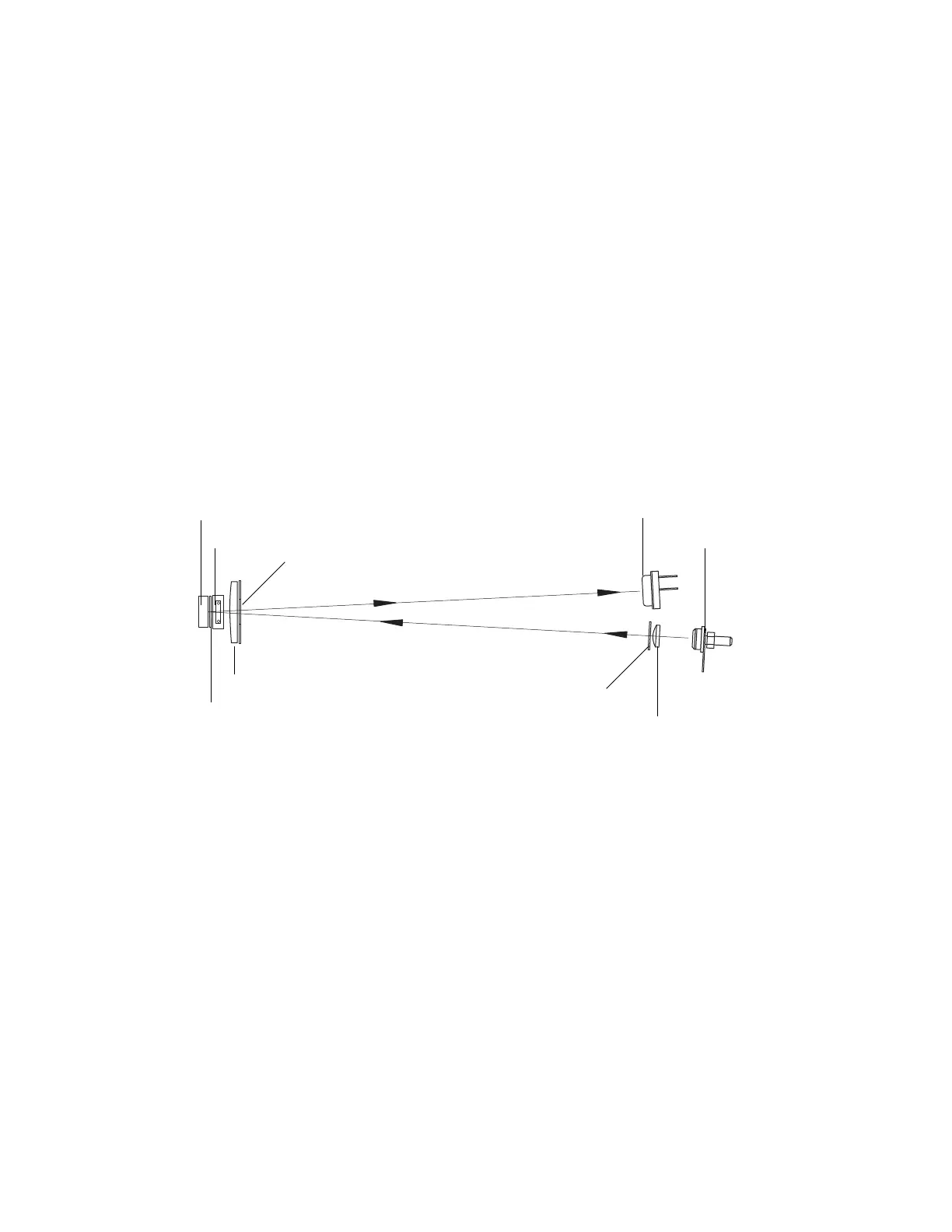
The following figure shows the path of the light beam as it passes through the
components in the optics bench assembly.
Figure 1–9: Optics bench assembly light path
The 2414 RI detector optics bench directs light as follows:
• Light from the LED is focused by the focusing lens through the aperture and
collimating lens, to form a beam.
• The light beam passes through the sample and reference sides of the flow cell to
the mirror.
• The light beam is reflected back through both sides of the flow cell and the
collimating lens to the dual-element photodiode.
The difference in the amount of light striking the elements of the photodiode (because
of sample refraction) results in a deflection from the baseline on the chromatogram.
1.3.7 Electronics
The 2414 RI detector has both analog and digital components and includes a
front-panel keyboard and these printed circuit (PC) boards and their interconnections:
Mirror
Flow cell
Stray light mask
Flow lens cell
Mirror mask
Dual element photodiode
LED
LED mask
LED lens