June 11, 2015, 715004754 Rev. A
Page 51
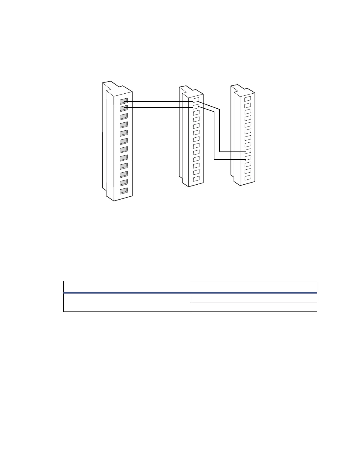
Figure 3–7: Chart mark and autozero connections between the Alliance
e2695 separations module and detector
3.4.2 Connecting to a data control system using analog
signals
To send an integrator analog output signal (–2 V to +2 V) from the 2414 RI detector
to chromatography data software (through a two-channel eSAT/IN Module), make the
connections shown in the table and figure, below.
Table 3–7: Analog output connections to the eSAT/IN module
eSAT/IN module connector Detector (connector B)
CHANNEL 1 Pin 9 Detector Out + (white)
Pin 10 Detector Out – (black)
Alliance e2695
separations module
connector B
2414 connector B 2414 connector A
Inject start + 1
Inject start - 2
Autozero +
1
Autozero -
2
9 + Chart Mark
10 - Chart Mark