June 11, 2015, 715004754 Rev. A
Page 50
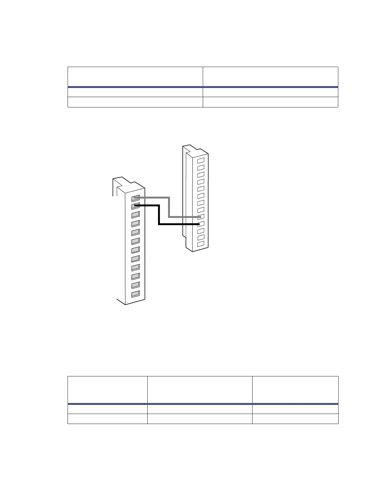
Figure 3–6: Chart mark connections between the Alliance e2695
separations module and the 2414 RI detector
3.4.1.3 Generating chart mark and autozero signals
To generate both a chart mark and an autozero signal from the Alliance e2695
separations module to the 2414 RI detector, make the connections shown in the table
and figure below.
Table 3–5: 2414 RI detector connections to an Alliance e2695 separations
module
Alliance e2695 separations module
(connector B)
Detector (connector A)
Pin 1 Inject Start Pin 9 Chart Mark +
Pin 2 Inject Start Pin 10 Chart Mark –
Table 3–6: Detector connections to an Alliance e2695 separations module
Alliance e2695
separations module
(connector B)
Detector (connector B) Detector (connector A)
Pin 1 Inject Start Pin 1 Autozero + Pin 9 Chart Mark +
Pin 2 Inject Start Pin 2 Autozero – Pin 10 Chart Mark –
Red
Black
Inject Start
Inject Start
Ground
Stop Flow+
Stop Flow–
Hold Inject 1+
Hold Inject 1–
Hold Inject 2+
Hold Inject 2–
Ground
Chart Out+
Chart Out–
1
2
3
4
5
6
7
8
9
10
11
12
1 + Inject Start
2 - Inject Start
3 Ground
4 + Purge
5 - Purge
6 + Polarity
7 - Polarity
8 Ground
9 + Chart Mark
10 - Chart Mark
11 Ground
12 + Switch
13 - Switch
2414 RI detector connector A
Alliance e2695
separations module
connector B