June 11, 2015, 715004754 Rev. A
Page 52
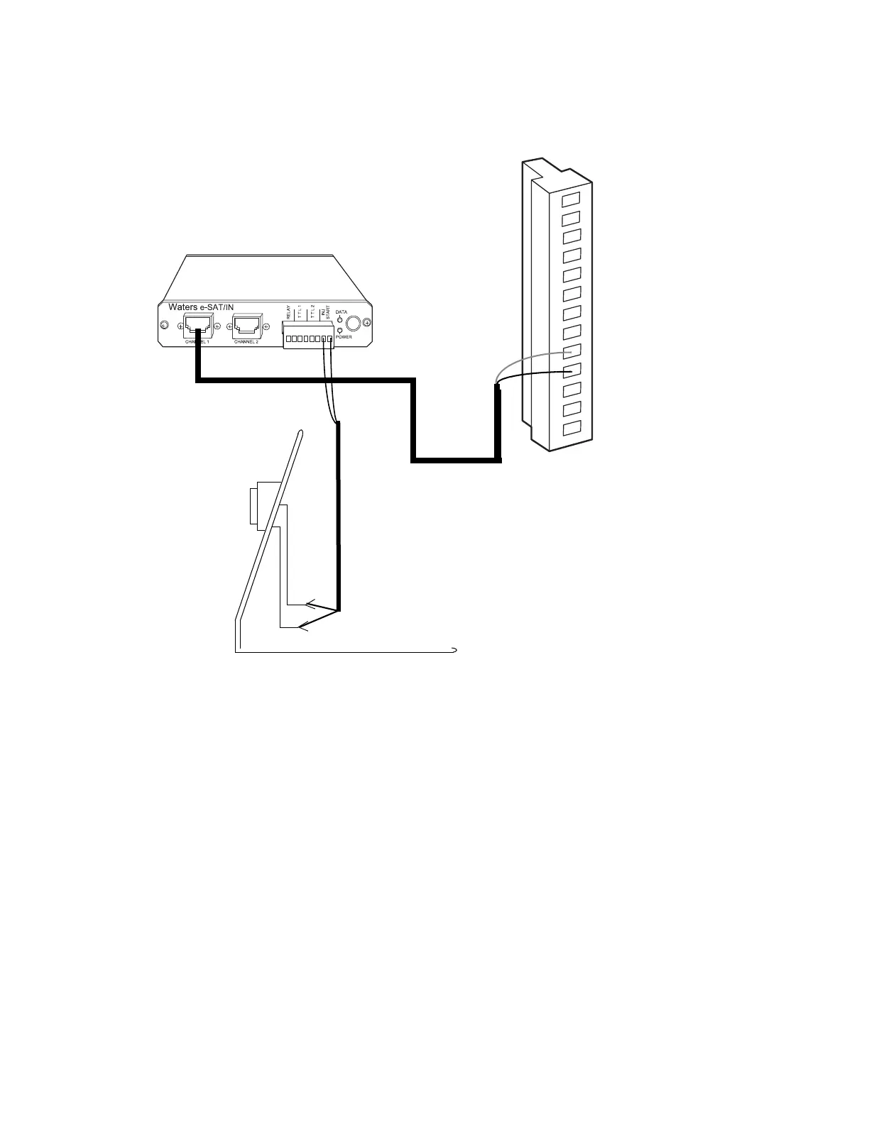
Figure 3–8: Analog output connections to the eSAT/IN module
3.4.3 Connecting injection trigger signals
The 2414 RI detector accepts the following injection trigger signals from a manual
injector:
• Auto-zero signal to automatically adjust the zero offset of the detector each
time the injector makes an injection
• Chart mark signal from a contact closure signal with each injection
• Inject start signal from a contact closure signal with each injection
Each time the detector receives a signal from a manual injector, it performs the
corresponding autozero, inject start, or chart mark function.
To send an autozero or chart mark signal from a manual injector to the detector, make
the connections shown in the tables and figures, below:
2414 RI detector connector B
eSAT/IN module
1 + Autozero
2 - Autozero
3 Ground
4 + Recycle Valve
5 - Recycle Valve
6 + Polarity Enabl
7 - Polarity Enable
8 Ground
9 + Detector Out
10 - Detector Out
11 Ground
12 + Auxiliary Out
13 - Auxiliary Out