June 11, 2015, 715004754 Rev. A
Page 48
Requirement: To meet the regulatory requirements of immunity from external
electrical disturbances that can affect the performance of this instrument, do not use
cables longer than 9.8 feet (3 meters) when you make connections to the
analog-out/event-in connectors. In addition, you must always connect the shield of
the cable to ground at one instrument only.
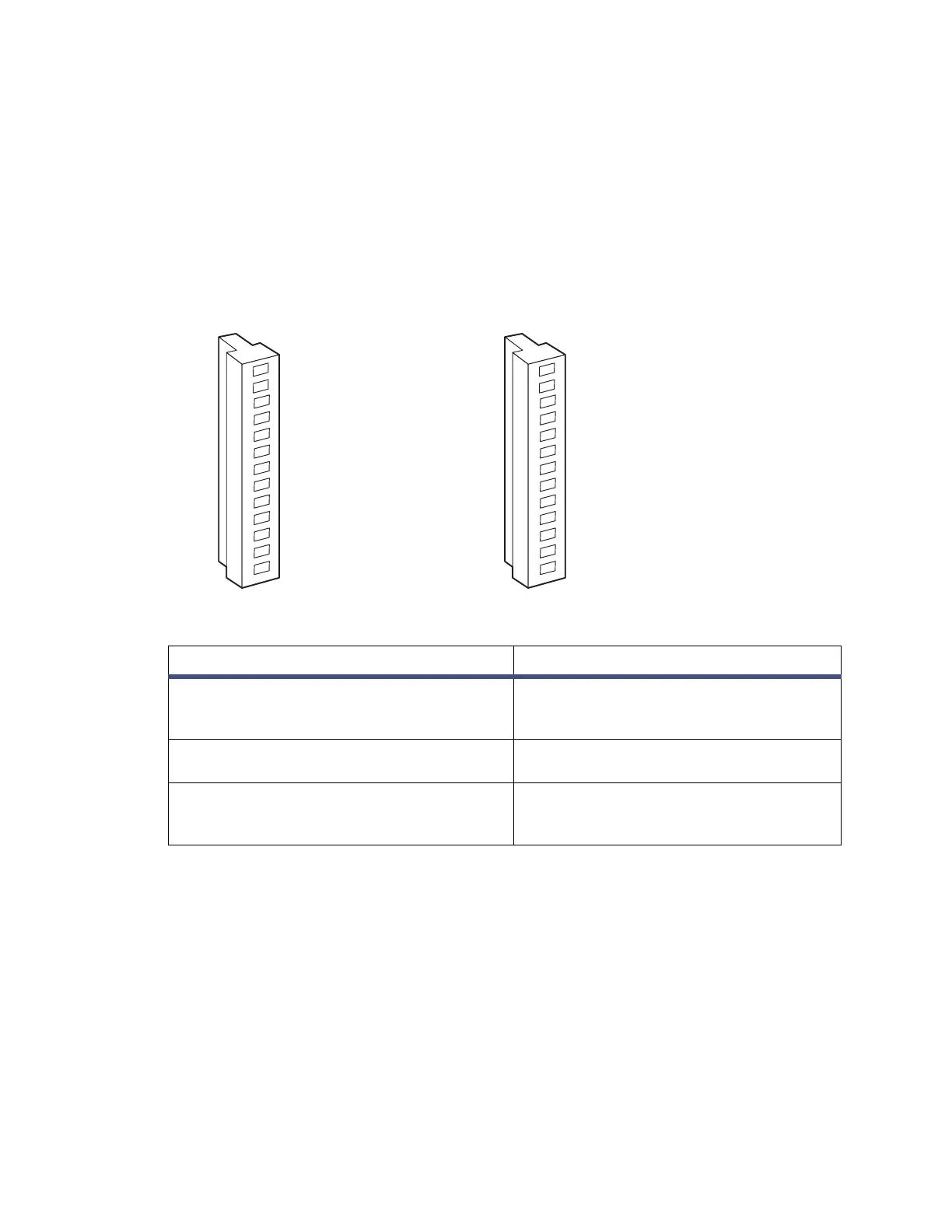
The following figure and table describe the two I/O connectors (and their
corresponding pin-outs) on the detector’s rear panel.
Figure 3–4: Rear panel analog-out/event-in connectors
3.4.1 Connecting to a standalone Alliance e2695
separations module
When you use the Alliance e2695 separations module as a standalone controller (that
is, not on an Ethernet or IEEE-488 bus interface or under data system control), you
can make the following signal connections using the 2414 RI detector’s
analog-out/event-in connectors:
• Autozero on inject
• Chart mark on inject
• Both chart mark and autozero on inject
•Inject start
Table 3–3: 2414 RI detector analog-out/event-in connections
Signal Connections Description
Chart Mark, Polarity and Polarity Enable,
Autozero, Purge, Recycle, and Inject Start
Accept TTL-level (0 to +5 V) or contact
closure signals from an external
instrument
Detector Out Sends a ±2 V (full scale) signal to an
integrator or computer
Auxiliary Out Sends a ±2 V (full scale) signal to an
integrator or computer (Temperature
Data)
B (inputs and outputs)
A (inputs and outputs)
1 + Autozero
2 - Autozero
3 GROUND
4 + Recycle Valve
5- Recycle Valve
6 + Polarity Enable
7 - Polarity Enable
8 GROUND
9 + Detector Out
10 - Detector Out
11 GROUND
12 + Auxiliary Out
13 - Auxiliary Out
1 + Inject Start
2 - Inject Start
3 GROUND
4 + Purge
5 - Purge
6 + Polarity
7 - Polarity
8 GROUND
9 + Chart Mark
10 - Chart Mark
11 GROUND
12 + Switch
13 - Switch