English
INSTALLATIONANDCONNECTION
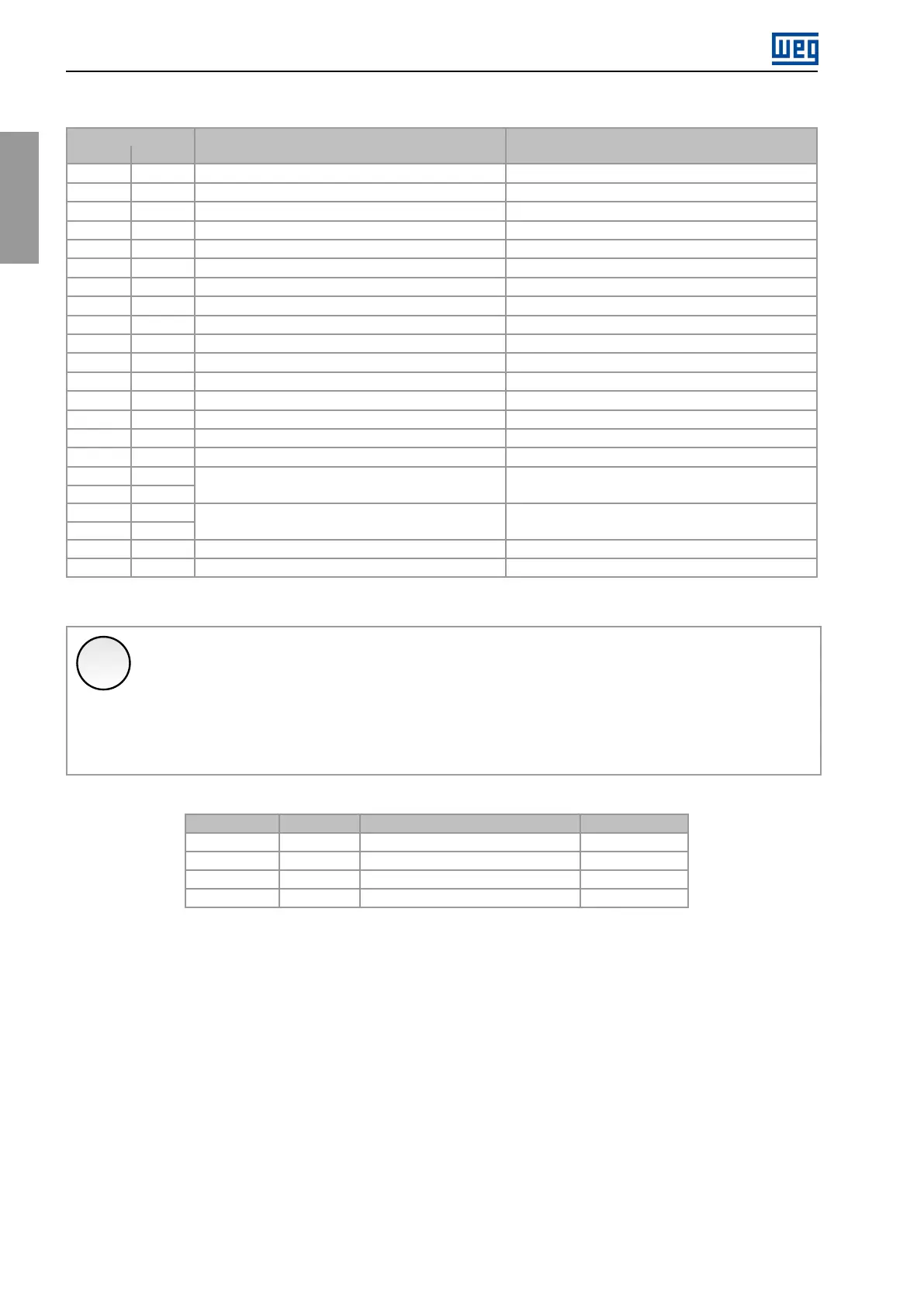
Table3.11:XC1connector(CFW900-IOS)
ConnectorXC1
PinName
Description
(1)
DefaultFunction(ifany)
1AO1
AnalogOutput1Speed
2AO2
AnalogOutput2Motorcurrent
3,8,18,26GND
Controlcircuitreference
4C
RS-485interfacereference
5A(-)
RS-485interfacenegative
6B(+)
RS-485interfacepositive
7VIN
+24Vdcexternalpowersupplyinput
9,25VOUT
+24Vdcpowersupplyoutput
10DI1
Digitalinput1Run/Stop(Onlyinremotemode2)
11DI2
Digitalinput2
12DI3
Digitalinput3
13DI4
Digitalinput4
14DI5
Digitalinput5InputAforencoder
15DI6
Digitalinput6InputBforencoder
16COM
Commonofthedigitalinputs
1710V
10Vpowersupplyforpotentiometer
19AI1+
20AI1-
Differentialanaloginput1Speedreference(onlyinremotemode2)
21AI2+
22AI2-
Differentialanaloginput2
23DO1
Digitaloutput1
24DO2
Digitaloutput2
(1)
FormoreinformationseethedetailedspecificationinTable8.11.
✓
NOTE!
ThedigitaloutputsoftheCFW900-IOShavefreewheelingdiodesforthe24Vdcpowersupplyof
theinvertercontrol(inverterinternalpowersupplyorexternalpowersupplyconnectedtoVIN).Ifa
separateexternal24Vdcpowersupplyisusedtopowertheloadsofthedigitaloutputs,thestateof
theoutputswillremainindeterminateaslongasthe24Vpowersupplyoftheinvertercontrolisnot
energized.Ifthischaracteristicisunwanted,theCFW900-REL-01orCFW900-IOD-01outputsmust
beused.
Table3.12:ConfigurationofDIPswitchesforselectingthetypeofsignalontheCFW900-IOSanaloginputs/outputs
Input/OutputDIPswitchDIPposition:Selectedmode
(1)
FactoryDefault
AI1S3:1V:-10a10V;I:4a20mA/0a20mAV
AI2S3:2V:-10a10V;I:4a20mA/0a20mAV
AO1S3:3V:0a10V;I:4a20mA/0a20mAV
AO2S3:4V:0a10V;I:4a20mA/0a20mAV
(1)
Theparametersreferringtotheinputs/outputsalsoneedtobeconfigured.Refertothe
programmingmanual.
40|CFW900