English
INSTALLATIONANDCONNECTION
Table3.10:Descriptionofcontrolconnections
Item
Description
1
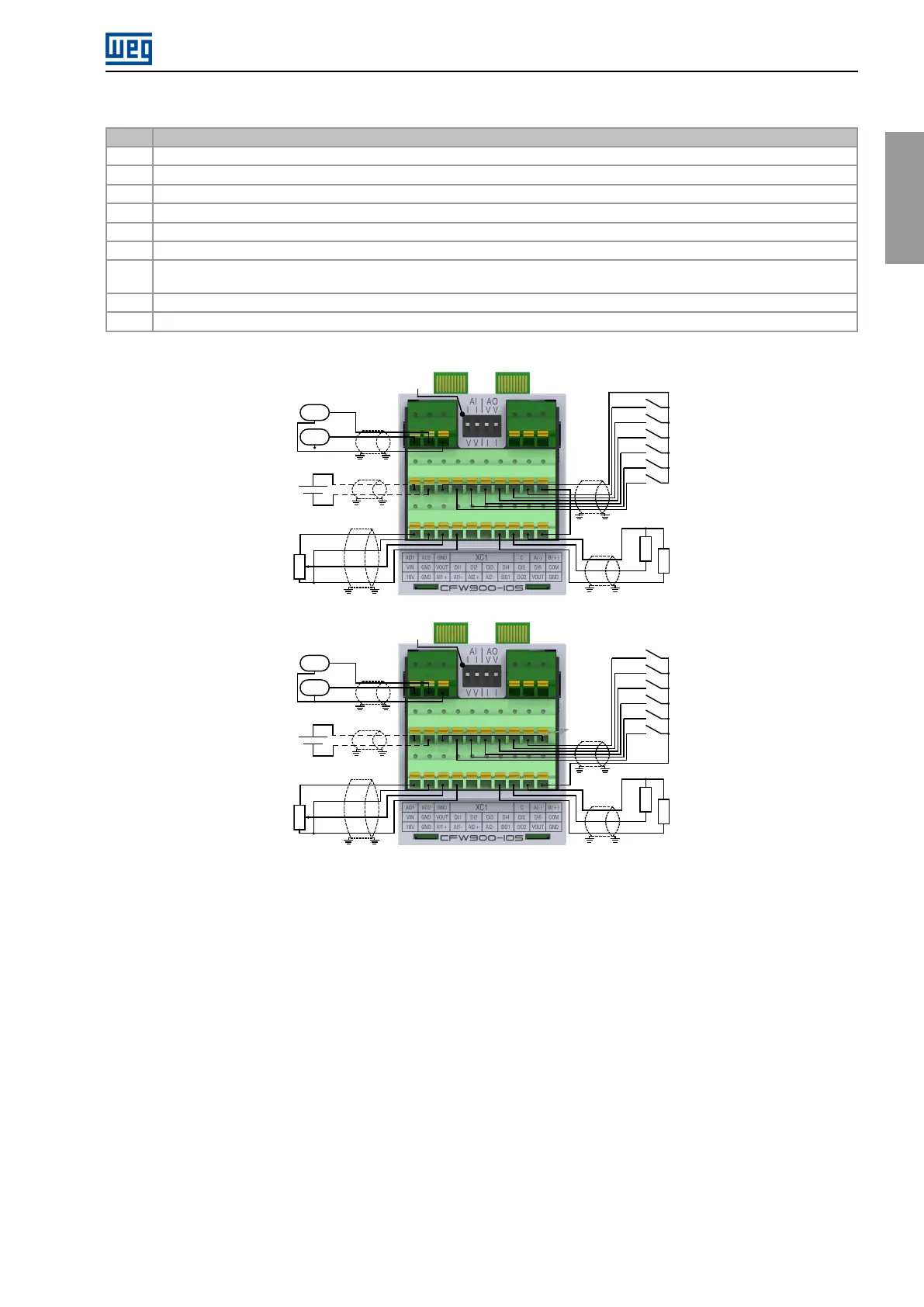
XC1Connector(CFW900-IOS):digitalandanaloginputsandoutputs,inputforexternalpowersupplyandRS-485communication
2
XC2Connector(safetymodule):STOandSS1-tfunctions
3
XC3connector(microSDcardslot):allowscopyingparametersandstoringSoftPLCprograms(seetheprogrammingmanual)
4
XC4AandXC4Bconnectors:dualportethernetconnection(RJ45)(seetheethernetcommunicationmanual)
5
DIPswitchesS1andS2:safetymoduleconfiguration
6
XC6connector:DB9connectorforconnectingtheHMI/remoteHMI
7
BackplaneCFW900-4SLOTS:providesfourslotstoconnectaccessories.Bydefault,slotAistakenbytheCFW900-REL-01.It
canbereplacedbytheCFW900-7SLOTS,whichhassevenslotsforaccessories
8
XC30(CFW900-REL-01):Relayoutput
9
CR2032batteryforrealtimeclock.Usenon-conductivepliersortweezerstoremove/replacethebattery
VIN (See 3.2.6.2)
GND
AI1-
AI1+
GND
10V
DI1
DI2
DI3
DI4
DI5
DI6
VOUT
DO1
AMP
RPM
GND
AO2
AO1
DO2
VOUT
1 2
3
4
5
6
7 8 9 10
11 12
13
14
15 16
17
18 19 20
21 22
23
24
25 26
COM
1 2
3
4
S3
(a)InputsconfiguredinPNPmode(standardversion)
VIN (See 3.2.6.2)
GND
AI1-
AI1+
GND
10V
DI1
DI2
DI3
DI4
DI5
DI6
GND
DO1
AMP
RPM
GND
AO2
AO1
DO2
VOUT
1 2
3
4
5
6
7 8 9 10
11 12
13
14
15 16
17
18 19 20
21 22
23
24
25 26
COM
S3
1 2
3
4
(b)InputsconfiguredinNPNmode
Figure3.20:(a)and(b)ConnectionexamplesonXC1(CFW900-IOS)
CFW900|39