3-11Maintenance
16-1408348
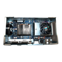
Shown below are the JUR SPI and BIOS sockets unpopulated, Figure 3-22 (A), the JUR SPI
with the BIOS socket unpopulated, Figure 3-22 (B), the BIOS with the JUR SPI socket
unpopulated, Figure 3-22 (C), and both the JUR SPI and BIOS sockets populated,
Figure 3-22 (D).
Figure 3-22 Both sockets unpopulated (top left), BIOS socket unpopulated (top right), JUR SPI socket
unpopulated (bottom left), and both sockets populated (bottom right).
2 If the chip is to be reinstalled, set aside in a safe location.
Install the JUR SPI Assembly or BIOS Firmware Assembly
Complete the following steps below to install the JUR SPI Assembly or BIOS Firmware Assembly.
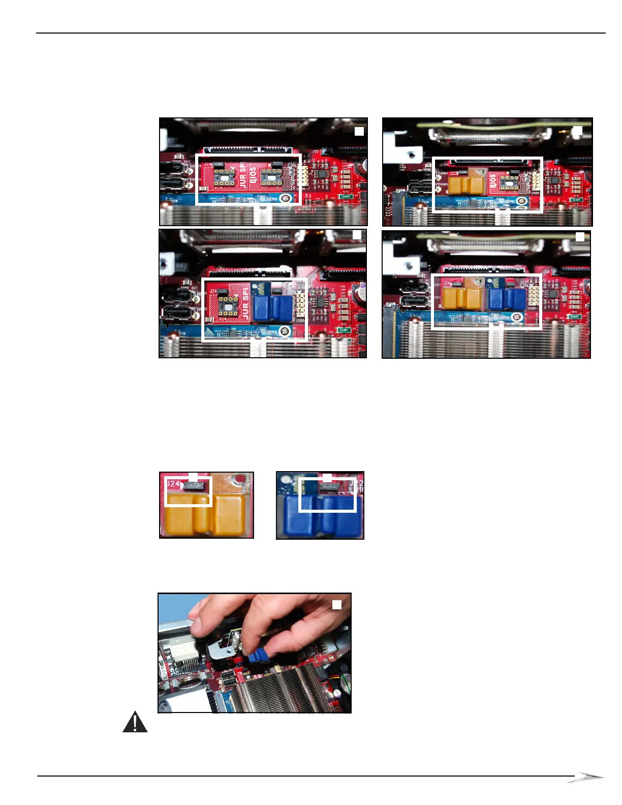
1 Confirm that the appropriate EPROM version is on the appropriate side of the board. The “L”
notch, Figure 3-23 (A), should line up with the post header on the board.
Figure 3-23 Lining up post header with “L” notch on board.
2 Use guide pins to position assembly and lock into socket, Figure 3-24 (A).
Figure 3-24 Using guide pins to position assembly
(BIOS Assembly shown).
CAUTION: Do not use excessive force when installing the JUR SPI Assembly or BIOS Firmware
Assembly. If it does not install easily, ensure the assembly is positioned properly and the leads are
not bent.
 Loading...