1-5About CPU-NXT 3.2
16-1408348
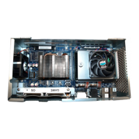
About
CPU-NXT 3.2
This section contains general information about CPU-NXT 3.2, Figure 1-5.
Figure 1-5 CPU-NXT 3.2.
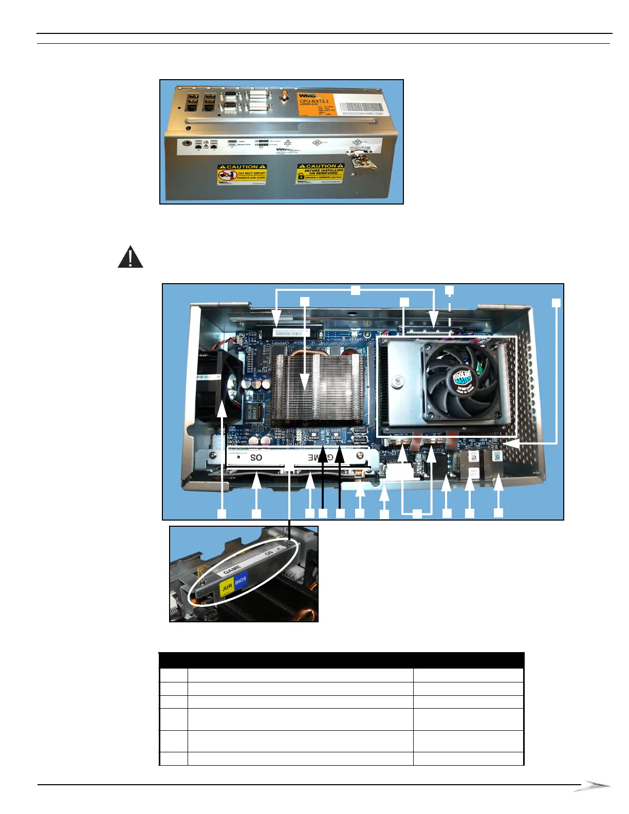
CPU-NXT 3.2 Board
Identification
Reference Figure 1-6 and Table 1-1 to identify the components on the PCB.
CAUTION: Do not remove the PCB from the enclosure.
Figure 1-6 Layout of CPU-NXT 3.2 PCB and with SSD Bracket (bottom closeup).
Table 1-1 Layout of CPU-NXT 3.2.
ID Connector Connector Position
A General I/O Blind Mate Connector P1, P2
B PCI Express x16 Video Card J17
C Reset Button SW1
D SDRAM Memory Module [located underneath CPU
Processor Heat Sink Fan (E)
J2 (COMe CPU Module)
E CPU Module and COM-EXPRESS
CPU Processor Heat Sink Fan
J18
F CPU-NXT 3.2 Enclosure Fan J14
 Loading...