4-2
Chapter 4: Troubleshooting
Aug 2012
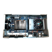
CPU-NXT 3.2 LEDs When an LED on the CPU-NXT 3.2 is not lit, check the meaning in Table 4-2 to identify where the
problem exists.
When an LED on the CPU-NXT 3.2 is not operating properly, consult the Position * column.
No video (power indicator LEDs are
lit).
Confirm the following:
video cables are installed in the proper ports.
COMe CPU Module is receiving power.
BIOS is properly installed; see Install the JUR SPI Assembly or BIOS
Firmware Assembly on page 3-11.
Display prompts user to use the
touch screen to select an action
while performing RAM Clear.
The two options given are as follows:
clear NVRAM and EEPROM
except meters
clear NVRAM and EPROM
Confirm the following:
the RAM Clear CompactFlash card is installed in the OS CompactFlash slot.
SPI EPROM is installed and in the proper orientation.
if the SPI EPROM was previously installed in the incorrect orientation, it will
require a replacement.
all the pins of the SPI EPROM are free of damage and are inserted into their
corresponding sockets.
the non-conductive battery tabs are removed.
Error Text Displays:
PREPART DSS Signature Validation
failed
Confirm the following:
the non-conductive battery tabs were removed from the CPU-NXT 3.2
battery holder.
the OS and game CompactFlash Cards are installed into their corresponding
locations and are fully inserted. Complete the following steps to confirm:
1) Power down the game.
2) Remove the OS and game CompactFlash Cards.
3) Replace the OS and game CompactFlash Cards, ensuring they are
securely installed.
4) Power up the game.
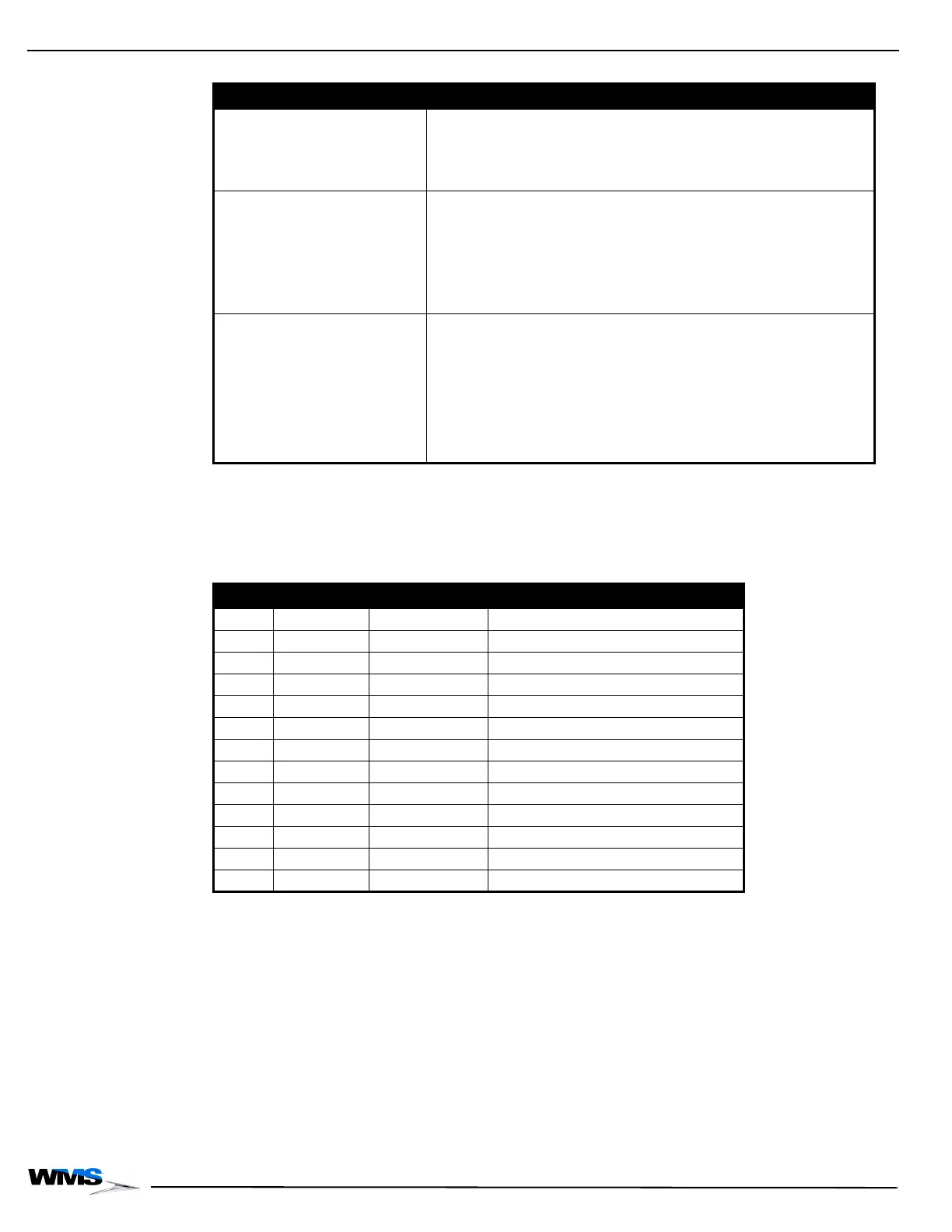
Table 4-1 Troubleshooting.
Symptoms Solutions
Table 4-2 CPU-NXT 3.2 LEDs.
LED Color Position * Meaning
D2 Red OFF IO Lock
D43 Green Toggle SSD A Access Indicator
D46 Green Toggle/OFF ** SSD B Access Indicator
D3 Green ON 3.3V Power
D7 Green ON 5V Power
D8 Green ON POWER GOOD
D13 Green ON 12V Power
D44 Green Toggle OS CompactFlash Access Indicator
D43 Green Toggle Game CompactFlash Access Indicator
D16 Green Toggle ATI Video Source
D17 Green OFF/Toggle *** Intel Video Source
D1A**** Green Toggle Game CompactFlash Access Indicator
D1B**** Green Toggle OS CompactFlash Access Indicator
* Position = Normally ON, Normally OFF, Toggle
** Depends if the SSD B is installed
*** Depends if a third video is attached
**** LEDs are on the PATA PCB and not on the mainboard
 Loading...