2-16
Chapter 2: Installation and Setup
Aug 2012
Checking/Installing
Jurisdictional SPI
and BIOS
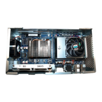
Depending on the jurisdiction, the Jurisdictional SPI (JUR SPI), Figure 2-7 (A), and BIOS,
Figure 2-7 (B), may not ship with CPU-NXT 3.2. Before installing CPU-NXT 3.2, verify that each chip
is fully seated.
NOTE: Figure 2-31 (C) shows orientation of the EPROMS.
Figure 2-31 JUR SPI and BIOS installed in CPU-NXT 3.2.
NOTE: If the BIOS ever requires replacing, see Removing/Installing Jurisdictional SPI and BIOS on
page 3-10, which explains how to replace the chip.
Installing the
Top Box LCD
DVI Cable
Complete the following steps to install the Top Box LCD DVI Cable (HD-029663-00-03).
1 Observe all appropriate safety and ESD precautions listed in Preventing Injury and Damage on
page 1-3.
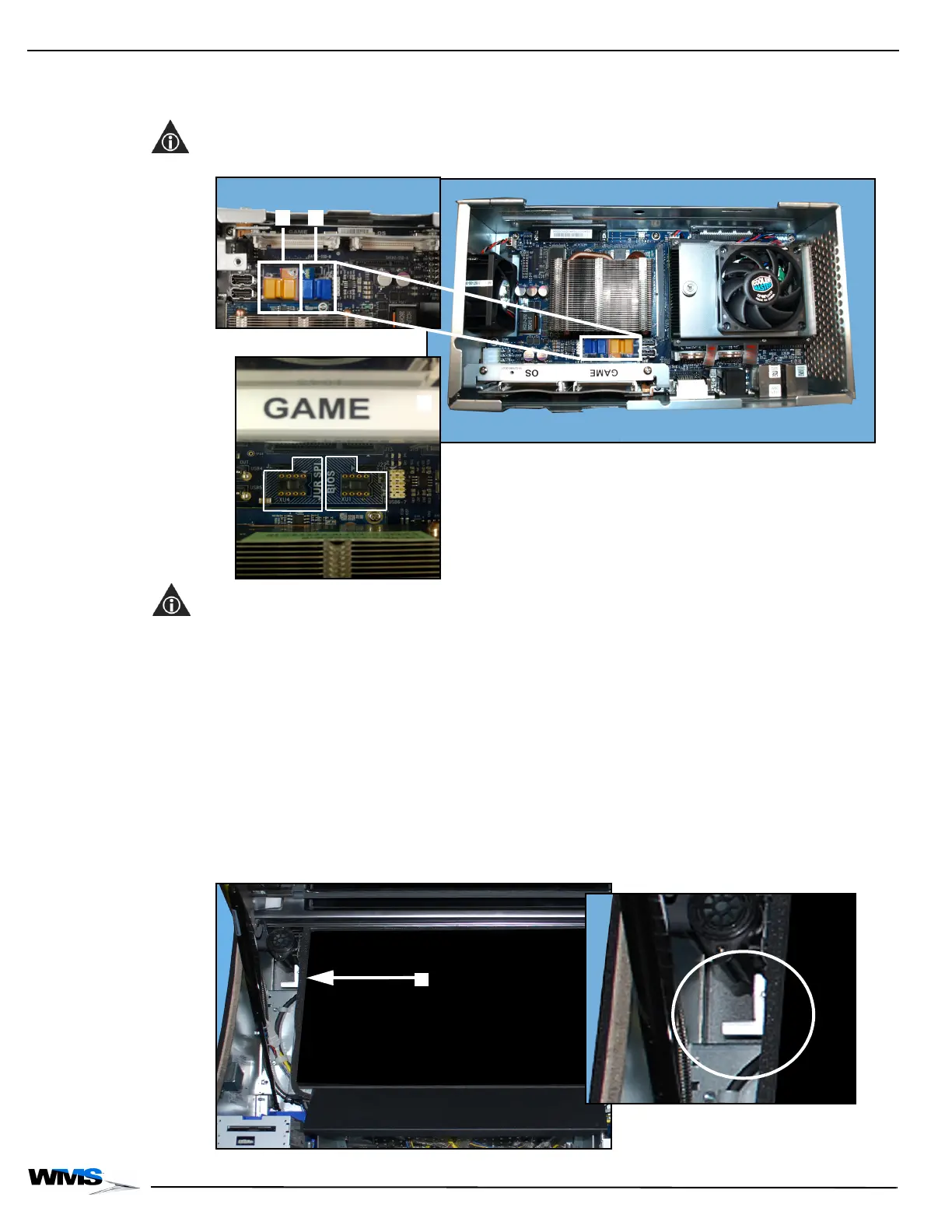
2 Pull firmly down on the Accessory/Top Box Crown Release Handle that hangs below the
Accessory/Top Box Crown Door on the left side of the LCD, Figure 2-32 (A), while lifting up on
the Accessory/Top Box Crown.
Once the Accessory/Top Box Crown Release Handle is pulled, the Accessory/Top Box Crown
Door is released but still safely held in place.
Figure 2-32 Accessory/Top Box Crown Release Handle next to LCD (close up on right).
 Loading...