Manual 37365A GCP-30 Series Packages - Genset Control
© Woodward Page 41/179
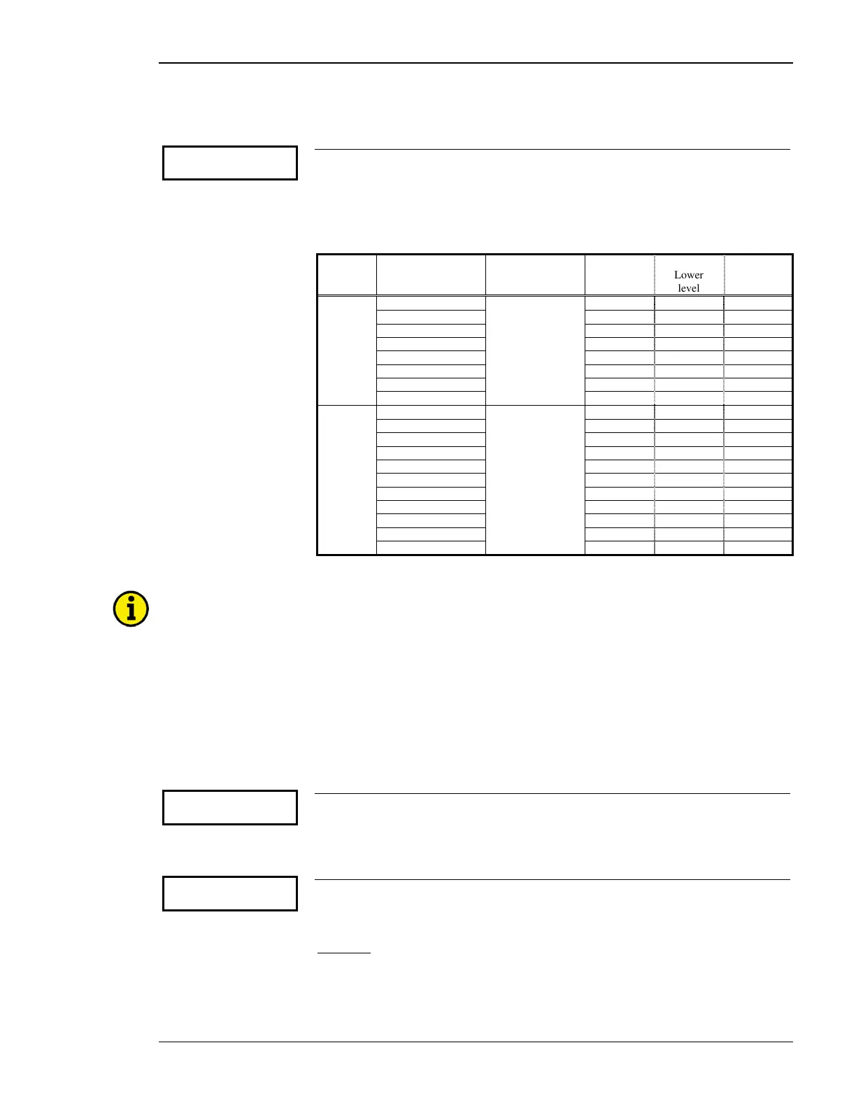
Analog Controller Output (BPQ, XPQ: Setting 'ANALOG/PWM')
Parameter 46
F/P contr.output
----------------
BPQ, XPQ
Frequency controller: output range see below
If "F/P contr.type" (Parameter 42) has been configured as "ANALOG", this para-
meter must be configured to the appropriate type of analog controller signal. The
range of the analog output is configured here. To switch from a current to a voltage
or PWM signal output a jumper must be installed between terminals 8/9. The avail-
able ranges are listed below
Type Setting in above
configuration
screen
Jumper
between
term. 8/9
Range
Lower
level
Upper
level
Current +/-20mA (+/-10V) no +/-20mA -20 mA +20 mA
+/-10mA (+/-5V) +/-10mA -10 mA +20 mA
0 to 10mA (0 to 5V) 0-10mA 0 mA 10 mA
0 to 20mA (0 to 10V) 0-20mA 0 mA 20 mA
4 to 20mA 4-20mA 4 mA 20 mA
10 to 0mA (5 to 0V) 10-0mA 10 mA 0 mA
20 to 0mA (10 to 0V) 20-0mA 20 mA 0 mA
20 to 4mA 20-4mA 20 mA 4 mA
Voltage +/-20mA (+/-10V) yes +/-10V -10 Vdc +10 Vdc
+/-10mA (+/-5V) +/-5V -5 Vdc +5 Vdc
+/-3V +/-3V -3 Vdc +3 Vdc
+/-2.5V +/-2.5V -2.5Vdc +2.5 Vdc
+/-1V +/-1V -1 Vdc +1 Vdc
0 to 10mA (0 to 5V) 0 to 5V 0 Vdc 5 Vdc
0.5V to 4.5V 0.5 to 4,5V 0.5 Vdc 4.5 Vdc
0 to 20mA (0 to 10V) 0 to 10V 0 Vdc 10 Vdc
10 to 0mA (5 to 0V) 5 to 0V 5 Vdc 0 Vdc
4.5V to 0.5V 4.5 to 0,5V 4.5 Vdc 0.5 Vdc
20 to 0mA (10 to 0V) 10 to 0V 10 Vdc 0 Vdc
NOTE
The control logic of the PWM signal can be inverted by following steps:
- Configure "F/P contr.type" (Parameter 42) as ANALOG.
- Configure "F/P contr.output" (Parameter 46 "F/P contr.output") with any of above inverted control
outputs
(i.e. "10 to 0mA (5 to 0V)", "4.5V to 0.5V", "20 to 0mA (10 to 0V)" or "20 to 4mA").
- Return to "F/P contr.type" (Parameter 42) by pressing "Select" and "Cursor→" simultaneously
.
- Configure "F/P contr.type" (Parameter 42) as PWM.
The PWM signal is now
inverted.
Parameter 47
Level PWM
----------------
BPQ, XPQ
Frequency controller: PWM level 3.0 to 10.0 V
If PWM has been selected in Parameter 42 the amplitude of the PWM signal can be
adjusted here.
Parameter 48
Stepper sign.frq
(min.) 000%
BPQ, XPQ
Frequency controller: minimum value 0 to 100%
This parameter permits the operator to clamp or limit the lower limit of the analog
output signal.
Example:
A 1 to 4V analog output is needed for the voltage controller to operate
properly. A jumper is installed on terminals 8/9 as described above and the analog
output signal of 0 to 5V is selected. The number to be configured as the minimum
output signal in this parameter is determined by dividing the desired lower limit by
the range of the signal (1V/5V = 0.20 or 20%). 20% is the value to be configured in
this parameter.

 Loading...


