June 2014
4-18
Xerox® WorkCentre® 3215/3225 Multifunction Printer Service Manual
REP 1.9
Repairs
Replacement
NOTE: Tapered Plastic Screws and Round Machine Screws are used to hold the cover to the
frame. Make sure that the Plastic Screws go into plastic components and Machine Screws go
into the metal frame.
1. Install the new Drive Motor (4 screws).
NOTE: The Frame is flexible and can be bowed out if the screws are not tightened in the
correct order.
Reinstall the Frame as follows so it seats flush against the printer’s internal modules.
2. Align the Frame on to the internal modules and shafts.
NOTE: Do Not fully tighten the screws in Step 3 until instructed.
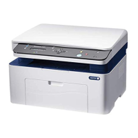
3. Install, but do not tighten, the following module screws (Figure 9):
a. The Exit Sensor Plate screws (2)
b. The Front Paper Path Module screws (3)
Figure 9 Frame Screw Installation
4. On the bottom of the Printer (Figure 7):
a. Install the Ground Clip and screw (1).
Tighten the screw.
b. Connect the Drive Motor Connector.
5. Install and tighten the Frame screws from the center of the Frame; to the front of the
printer, then to the rear of the Printer. Install the shaft bushings (2) (Figure 9).
a. Tighten the Front Paper Path Module screws (3) installed in Step 3b.
b. The ROS Support screws (2)
c. The Rear Paper Path Module screws (3)
d. Tighten all the Exit Sensor Plate screws (2) installed in Step 3a.
e. Shaft Bushings (2).
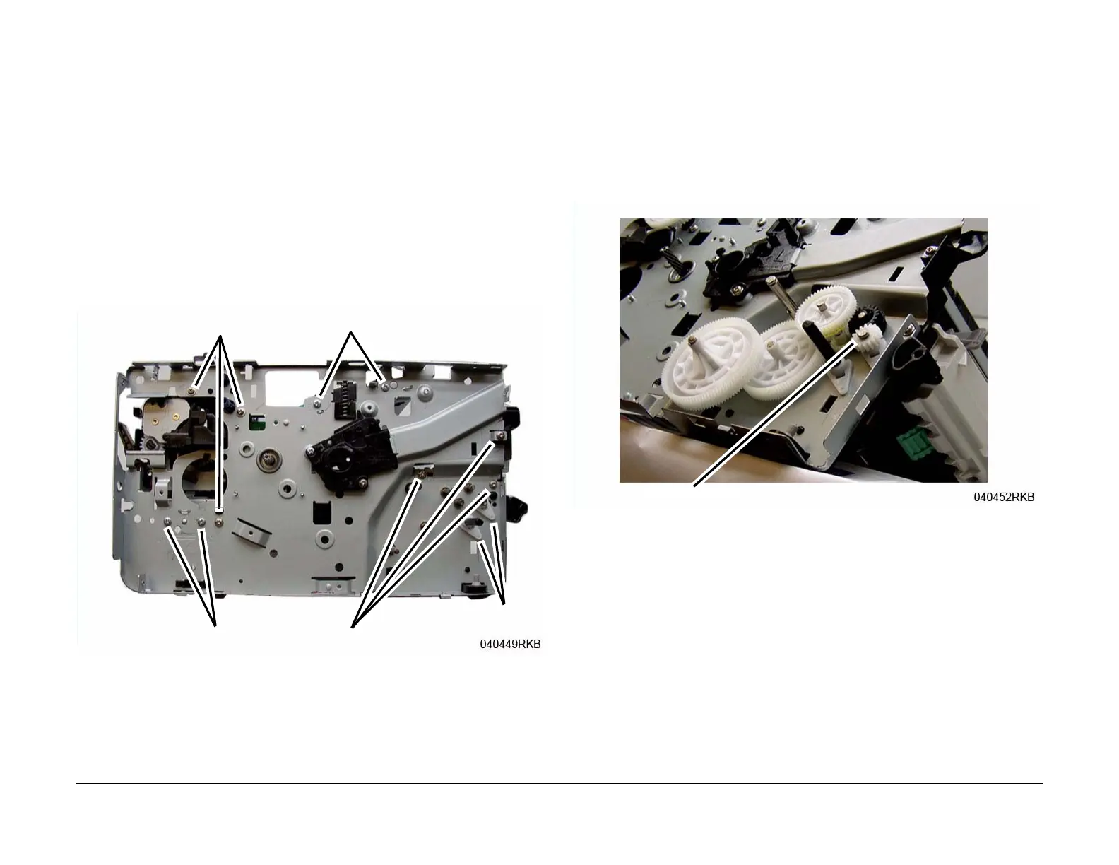
6. Reinstall the Drive Gears, and Snap Ring.
Refer to (Figure 10) for correct installation the Feed and Registration Drive Gears.
Figure 10 Feed and Registration Drive Gears
7. Install the remaining components in the reverse of removal.
When installing the Front Cover Support Arm make sure it is correctly placed on the Stop
Bracket (Figure 11).
Step 3a
Step 5b
Step 5c
Step 3b
Step 5e
Snap Ring