Spartan-3E Starter Kit Board User Guide www.xilinx.com 19
UG230 (v1.0) March 9, 2006
Discrete LEDs
R
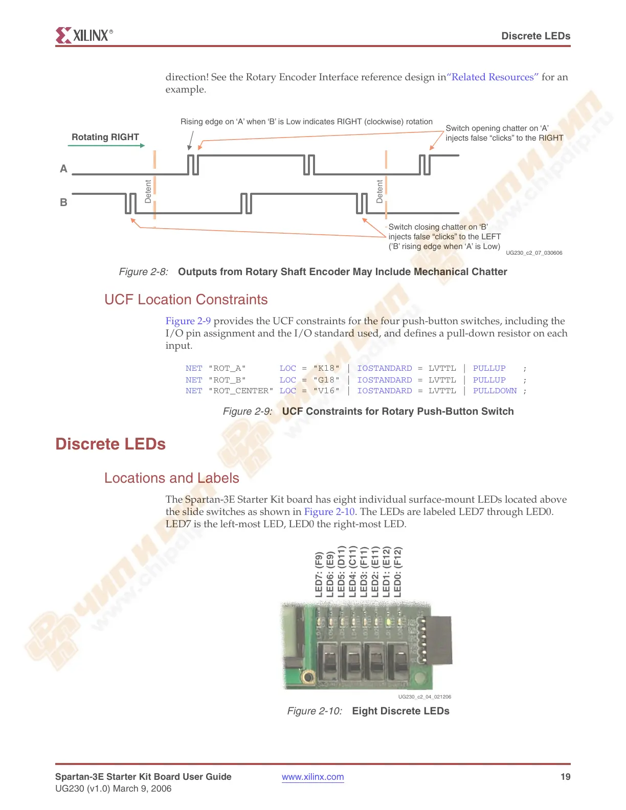
direction! See the Rotary Encoder Interface reference design in“Related Resources” for an
example.
UCF Location Constraints
Figure 2-9 provides the UCF constraints for the four push-button switches, including the
I/O pin assignment and the I/O standard used, and defines a pull-down resistor on each
input.
Discrete LEDs
Locations and Labels
The Spartan-3E Starter Kit board has eight individual surface-mount LEDs located above
the slide switches as shown in Figure 2-10. The LEDs are labeled LED7 through LED0.
LED7 is the left-most LED, LED0 the right-most LED.
Figure 2-8:
Outputs from Rotary Shaft Encoder May Include Mechanical Chatter
A
B
Detent
Detent
UG230_c2_07_030606
Rotating RIGHT
Switch closing chatter on ‘B’
injects false “clicks” to the LEFT
(’B’ rising edge when ‘A’ is Low)
Switch opening chatter on ‘A’
injects false “clicks” to the RIGHT
Rising edge on ‘A’ when ‘B’ is Low indicates RIGHT (clockwise) rotation
Figure 2-9:
UCF Constraints for Rotary Push-Button Switch
NET "ROT_A" LOC = "K18"
IOSTANDARD = LVTTL
PULLUP ;
NET "ROT_B" LOC = "G18" | IOSTANDARD = LVTTL | PULLUP ;
NET "ROT_CENTER" LOC = "V16" | IOSTANDARD = LVTTL | PULLDOWN ;
Figure 2-10:
Eight Discrete LEDs
UG230_c2_04_021206
LED7: (F9)
LED6: (E9)
LED5: (D11)
LED4: (C11)
LED3: (F11)
LED2: (E11)
LED1: (E12)
LED0: (F12)