Spartan-3E Starter Kit Board User Guide www.xilinx.com 87
UG230 (v1.0) March 9, 2006
Setting the FPGA Mode Select Pins
R
Control
Figure 11-4 provides the UCF constraints for the StrataFlash control pins, including the
I/O pin assignment and the I/O standard used.
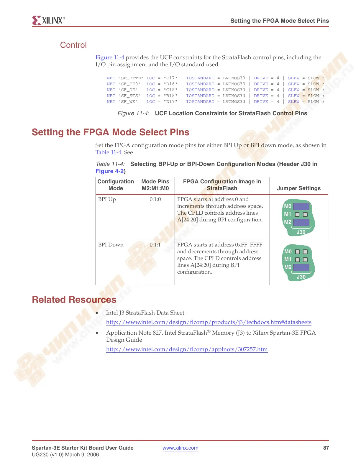
Setting the FPGA Mode Select Pins
Set the FPGA configuration mode pins for either BPI Up or BPI down mode, as shown in
Table 11-4. See
Related Resources
• Intel J3 StrataFlash Data Sheet
http://www.intel.com/design/flcomp/products/j3/techdocs.htm#datasheets
• Application Note 827, Intel StrataFlash
®
Memory (J3) to Xilinx Spartan-3E FPGA
Design Guide
http://www.intel.com/design/flcomp/applnots/307257.htm
Figure 11-4:
UCF Location Constraints for StrataFlash Control Pins
NET "SF_BYTE" LOC = "C17" | IOSTANDARD = LVCMOS33 | DRIVE = 4 | SLEW = SLOW ;
NET "SF_CE0" LOC = "D16" | IOSTANDARD = LVCMOS33 | DRIVE = 4 | SLEW = SLOW ;
NET "SF_OE" LOC = "C18" | IOSTANDARD = LVCMOS33 | DRIVE = 4 | SLEW = SLOW ;
NET "SF_STS" LOC = "B18" | IOSTANDARD = LVCMOS33 | DRIVE = 4 | SLEW = SLOW ;
NET "SF_WE" LOC = "D17" | IOSTANDARD = LVCMOS33 | DRIVE = 4 | SLEW = SLOW ;
Table 11-4:
Selecting BPI-Up or BPI-Down Configuration Modes (Header J30 in
Figure 4-2)
Configuration
Mode
Mode Pins
M2:M1:M0
FPGA Configuration Image in
StrataFlash Jumper Settings
BPI Up 0:1:0 FPGA starts at address 0 and
increments through address space.
The CPLD controls address lines
A[24:20] during BPI configuration.
BPI Down 0:1:1 FPGA starts at address 0xFF_FFFF
and decrements through address
space. The CPLD controls address
lines A[24:20] during BPI
configuration.
M0
M1
M2
J30
M0
M1
M2
J30