20 www.xilinx.com Spartan-3E Starter Kit Board User Guide
UG230 (v1.0) March 9, 2006
Chapter 2:
Switches, Buttons, and Knob
R
Operation
Each LED has one side connected to ground and the other side connected to a pin on the
Spartan-3E device via a 390Ω current limiting resistor. To light an individual LED, drive
the associated FPGA control signal High.
UCF Location Constraints
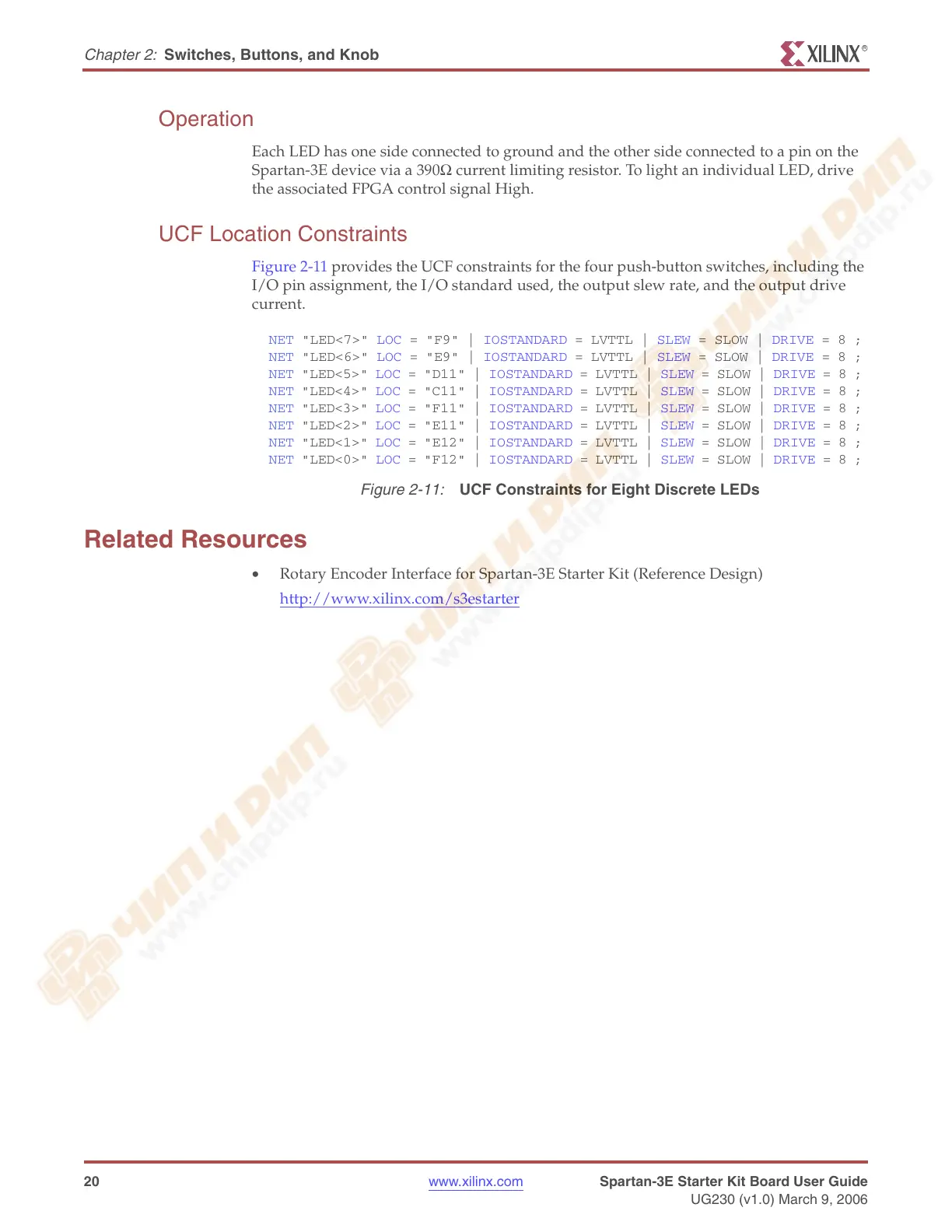
Figure 2-11 provides the UCF constraints for the four push-button switches, including the
I/O pin assignment, the I/O standard used, the output slew rate, and the output drive
current.
Related Resources
• Rotary Encoder Interface for Spartan-3E Starter Kit (Reference Design)
http://www.xilinx.com/s3estarter
Figure 2-11:
UCF Constraints for Eight Discrete LEDs
NET "LED<7>" LOC = "F9" | IOSTANDARD = LVTTL | SLEW = SLOW | DRIVE = 8 ;
NET "LED<6>" LOC = "E9" | IOSTANDARD = LVTTL | SLEW = SLOW | DRIVE = 8 ;
NET "LED<5>" LOC = "D11" | IOSTANDARD = LVTTL | SLEW = SLOW | DRIVE = 8 ;
NET "LED<4>" LOC = "C11" | IOSTANDARD = LVTTL | SLEW = SLOW | DRIVE = 8 ;
NET "LED<3>" LOC = "F11" | IOSTANDARD = LVTTL | SLEW = SLOW | DRIVE = 8 ;
NET "LED<2>" LOC = "E11" | IOSTANDARD = LVTTL | SLEW = SLOW | DRIVE = 8 ;
NET "LED<1>" LOC = "E12" | IOSTANDARD = LVTTL | SLEW = SLOW | DRIVE = 8 ;
NET "LED<0>" LOC = "F12" | IOSTANDARD = LVTTL | SLEW = SLOW | DRIVE = 8 ;