76 www.xilinx.com Spartan-3E Starter Kit Board User Guide
UG230 (v1.0) March 9, 2006
Chapter 10:
Analog Capture Circuit
R
SPI Control Interface
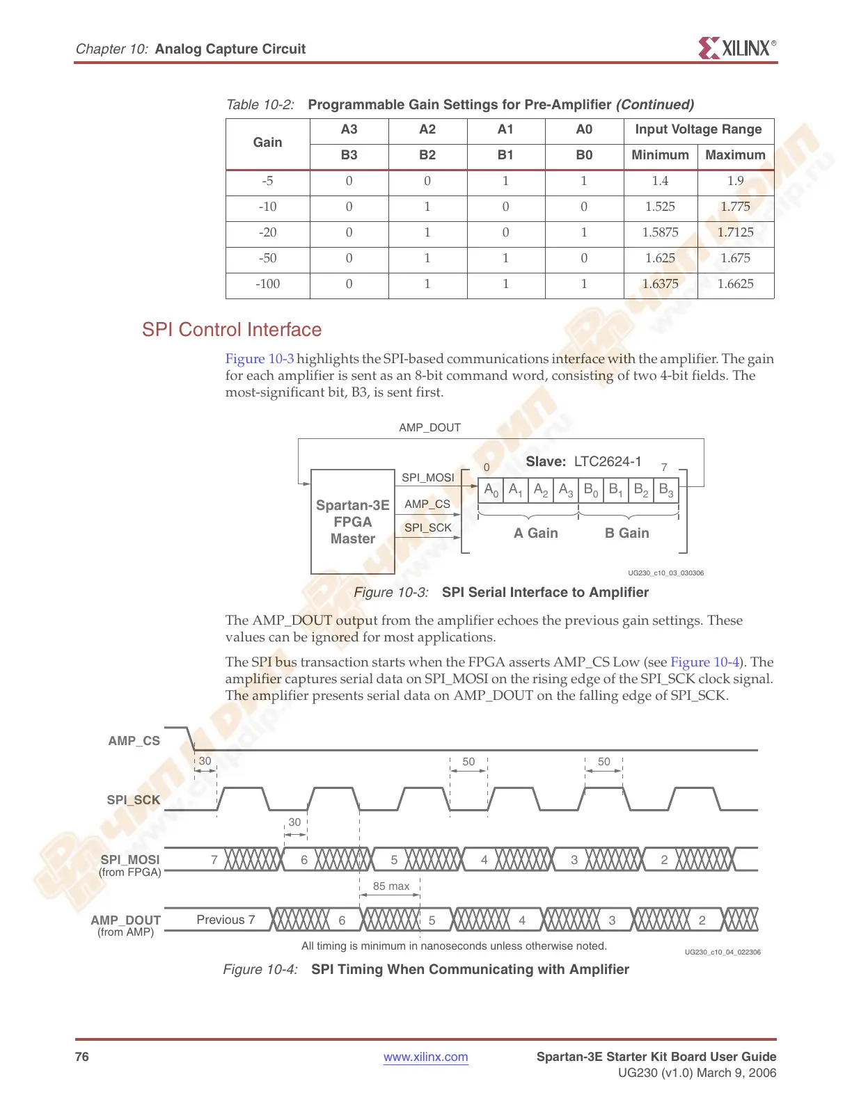
Figure 10-3 highlights the SPI-based communications interface with the amplifier. The gain
for each amplifier is sent as an 8-bit command word, consisting of two 4-bit fields. The
most-significant bit, B3, is sent first.
The AMP_DOUT output from the amplifier echoes the previous gain settings. These
values can be ignored for most applications.
The SPI bus transaction starts when the FPGA asserts AMP_CS Low (see Figure 10-4). The
amplifier captures serial data on SPI_MOSI on the rising edge of the SPI_SCK clock signal.
The amplifier presents serial data on AMP_DOUT on the falling edge of SPI_SCK.
-500111.41.9
-1001001.5251.775
-2001011.58751.7125
-5001101.6251.675
-10001111.63751.6625
Table 10-2:
Programmable Gain Settings for Pre-Amplifier
(Continued)
Gain
A3 A2 A1 A0 Input Voltage Range
B3 B2 B1 B0 Minimum Maximum
Figure 10-3:
SPI Serial Interface to Amplifier
7
Spartan-3E
FPGA
Master
0
A
1
A
2
A
3
A
0
B
1
B
2
B
3
B
0
A Gain B Gain
Slave: LTC2624-1
AMP_DOUT
SPI_MOSI
AMP_CS
SPI_SCK
UG230_c10_03_030306
Figure 10-4:
SPI Timing When Communicating with Amplifier
SPI_SCK
AMP_CS
SPI_MOSI
AMP_DOUT
765432
30
5050
30
65432
85 max
All timing is minimum in nanoseconds unless otherwise noted.
(from AMP)
(from FPGA)
Previous 7
UG230_c10_04_022306