Spartan-3E Starter Kit Board User Guide www.xilinx.com 121
UG230 (v1.0) March 9, 2006
Six-Pin Accessory Headers
R
Six-Pin Accessory Headers
The 6-pin accessory headers provide easy I/O interface expansion using the various
Digilent Peripheral Modules (see “Related Resources,” page 124). The location of the 6-pin
headers is provided in Figure 15-1, page 113.
Header J1
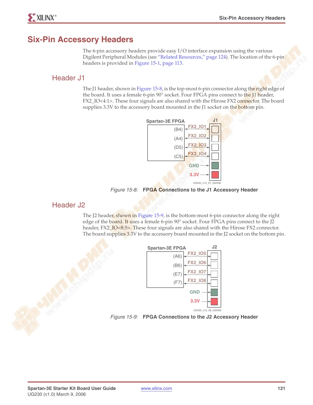
The J1 header, shown in Figure 15-8, is the top-most 6-pin connector along the right edge of
the board. It uses a female 6-pin 90° socket. Four FPGA pins connect to the J1 header,
FX2_IO<4:1>. These four signals are also shared with the Hirose FX2 connector. The board
supplies 3.3V to the accessory board mounted in the J1 socket on the bottom pin.
Header J2
The J2 header, shown in Figure 15-9, is the bottom-most 6-pin connector along the right
edge of the board. It uses a female 6-pin 90° socket. Four FPGA pins connect to the J2
header, FX2_IO<8:5>. These four signals are also shared with the Hirose FX2 connector.
The board supplies 3.3V to the accessory board mounted in the J2 socket on the bottom pin.
Figure 15-8:
FPGA Connections to the J1 Accessory Header
J1
(B4)
FX2_IO1
(A4)
FX2_IO2
(D5)
FX2_IO3
(C5)
FX2_IO4
Spartan-3E FPGA
GND
3.3V
UG230_c12_07_022406
Figure 15-9:
FPGA Connections to the J2 Accessory Header
J2
(A6)
FX2_IO5
(B6)
FX2_IO6
(E7)
FX2_IO7
(F7)
FX2_IO8
Spartan-3E FPGA
GND
3.3V
UG230_c12_08_022406