46 www.xilinx.com Spartan-3E Starter Kit Board User Guide
UG230 (v1.0) March 9, 2006
Chapter 5:
Character LCD Screen
R
The CG RAM address counter can either remain constant after read or write operations, or
auto-increments or auto-decrements by one location, as defined by the I/D set by the Entry
Mode Set command.
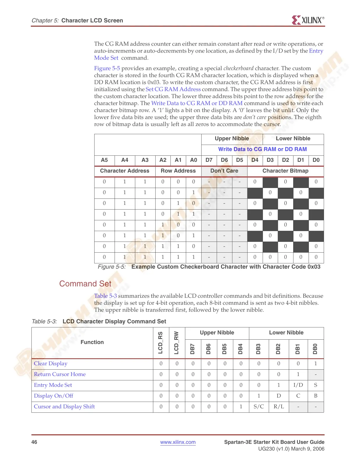
Figure 5-5 provides an example, creating a special checkerboard character. The custom
character is stored in the fourth CG RAM character location, which is displayed when a
DD RAM location is 0x03. To write the custom character, the CG RAM address is first
initialized using the Set CG RAM Address command. The upper three address bits point to
the custom character location. The lower three address bits point to the row address for the
character bitmap. The Write Data to CG RAM or DD RAM command is used to write each
character bitmap row. A ‘1’ lights a bit on the display. A ‘0’ leaves the bit unlit. Only the
lower five data bits are used; the upper three data bits are don’t care positions. The eighth
row of bitmap data is usually left as all zeros to accommodate the cursor.
Command Set
Table 5-3 summarizes the available LCD controller commands and bit definitions. Because
the display is set up for 4-bit operation, each 8-bit command is sent as two 4-bit nibbles.
The upper nibble is transferred first, followed by the lower nibble.
Upper Nibble Lower Nibble
Write Data to CG RAM or DD RAM
A5 A4 A3 A2 A1 A0 D7 D6 D5 D4 D3 D2 D1 D0
Character Address Row Address
Don’t Care Character Bitmap
011000
- - -01010
011001
- - - 10101
011010
- - -01010
011011
- - - 10101
011100
- - -01010
011101
- - - 10101
011110
- - -01010
011111
- - -00000
Figure 5-5:
Example Custom Checkerboard Character with Character Code 0x03
Table 5-3:
LCD Character Display Command Set
Function
LCD_RS
LCD_RW
Upper Nibble Lower Nibble
DB7
DB6
DB5
DB4
DB3
DB2
DB1
DB0
Clear Display 000000 0 0 0 1
Return Cursor Home 000000 0 0 1
-
Entry Mode Set 000000 0 1I/DS
Display On/Off 000000 1 D CB
Cursor and Display Shift 000001S/CR/L
- -