60 www.xilinx.com Spartan-3E Starter Kit Board User Guide
UG230 (v1.0) March 9, 2006
Chapter 7:
RS-232 Serial Ports
R
Figure 7-1 shows the connection between the FPGA and the two DB9 connectors. The
FPGA supplies serial output data using LVTTL or LVCMOS levels to the Maxim device,
which in turn, converts the logic value to the appropriate RS-232 voltage level. Likewise,
the Maxim device converts the RS-232 serial input data to LVTTL levels for the FPGA. A
series resistor between the Maxim output pin and the FPGA’s RXD pin protects against
accidental logic conflicts.
Hardware flow control is not supported on the connector. The port’s DCD, DTR, and DSR
signals connect together, as shown in Figure 7-1. Similarly, the port’s RTS and CTS signals
connect together.
UCF Location Constraints
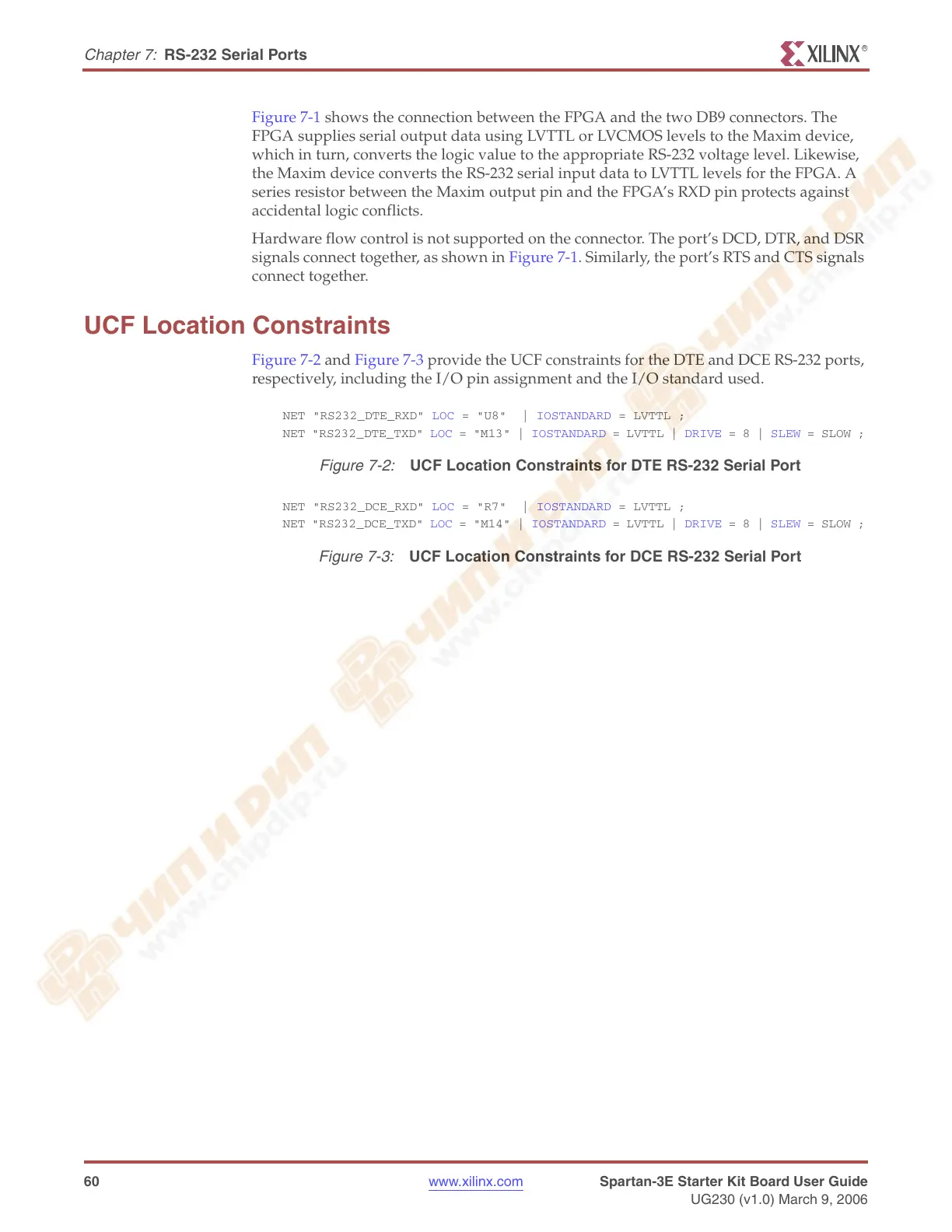
Figure 7-2 and Figure 7-3 provide the UCF constraints for the DTE and DCE RS-232 ports,
respectively, including the I/O pin assignment and the I/O standard used.
Figure 7-2:
UCF Location Constraints for DTE RS-232 Serial Port
Figure 7-3:
UCF Location Constraints for DCE RS-232 Serial Port
NET "RS232_DTE_RXD" LOC = "U8" | IOSTANDARD = LVTTL ;
NET "RS232_DTE_TXD" LOC = "M13" | IOSTANDARD = LVTTL | DRIVE = 8 | SLEW = SLOW ;
NET "RS232_DCE_RXD" LOC = "R7" | IOSTANDARD = LVTTL ;
NET "RS232_DCE_TXD" LOC = "M14" | IOSTANDARD = LVTTL | DRIVE = 8 | SLEW = SLOW ;