22 www.xilinx.com Spartan-3E Starter Kit Board User Guide
UG230 (v1.0) March 9, 2006
Chapter 3:
Clock Sources
R
Clock Connections
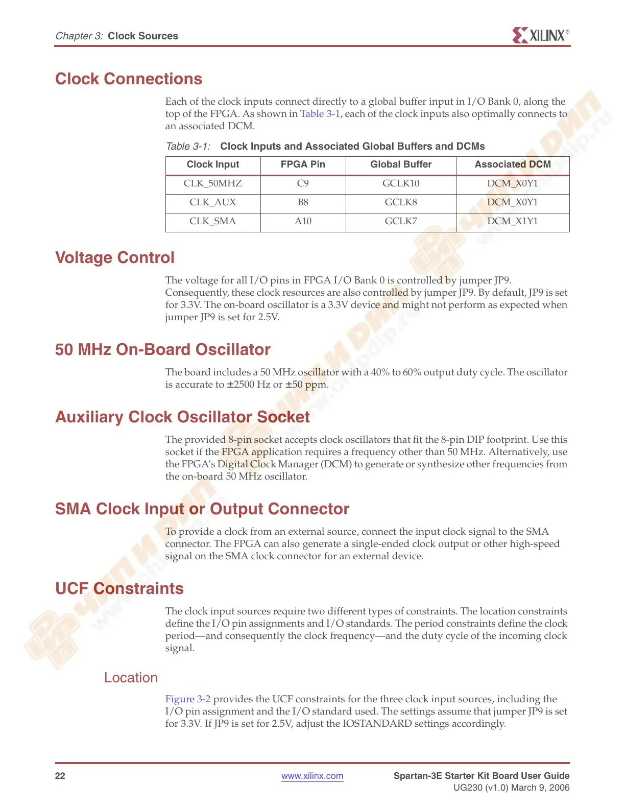
Each of the clock inputs connect directly to a global buffer input in I/O Bank 0, along the
top of the FPGA. As shown in Table 3-1, each of the clock inputs also optimally connects to
an associated DCM.
Voltage Control
The voltage for all I/O pins in FPGA I/O Bank 0 is controlled by jumper JP9.
Consequently, these clock resources are also controlled by jumper JP9. By default, JP9 is set
for 3.3V. The on-board oscillator is a 3.3V device and might not perform as expected when
jumper JP9 is set for 2.5V.
50 MHz On-Board Oscillator
The board includes a 50 MHz oscillator with a 40% to 60% output duty cycle. The oscillator
is accurate to
±2500 Hz or ±50 ppm.
Auxiliary Clock Oscillator Socket
The provided 8-pin socket accepts clock oscillators that fit the 8-pin DIP footprint. Use this
socket if the FPGA application requires a frequency other than 50 MHz. Alternatively, use
the FPGA’s Digital Clock Manager (DCM) to generate or synthesize other frequencies from
the on-board 50 MHz oscillator.
SMA Clock Input or Output Connector
To provide a clock from an external source, connect the input clock signal to the SMA
connector. The FPGA can also generate a single-ended clock output or other high-speed
signal on the SMA clock connector for an external device.
UCF Constraints
The clock input sources require two different types of constraints. The location constraints
define the I/O pin assignments and I/O standards. The period constraints define the clock
period—and consequently the clock frequency—and the duty cycle of the incoming clock
signal.
Location
Figure 3-2 provides the UCF constraints for the three clock input sources, including the
I/O pin assignment and the I/O standard used. The settings assume that jumper JP9 is set
for 3.3V. If JP9 is set for 2.5V, adjust the IOSTANDARD settings accordingly.
Table 3-1:
Clock Inputs and Associated Global Buffers and DCMs
Clock Input FPGA Pin Global Buffer Associated DCM
CLK_50MHZ C9 GCLK10 DCM_X0Y1
CLK_AUX B8 GCLK8 DCM_X0Y1
CLK_SMA A10 GCLK7 DCM_X1Y1