Table 46: TX Configurable Driver Ports (cont'd)
Port Dir
Clock
Domain
Description
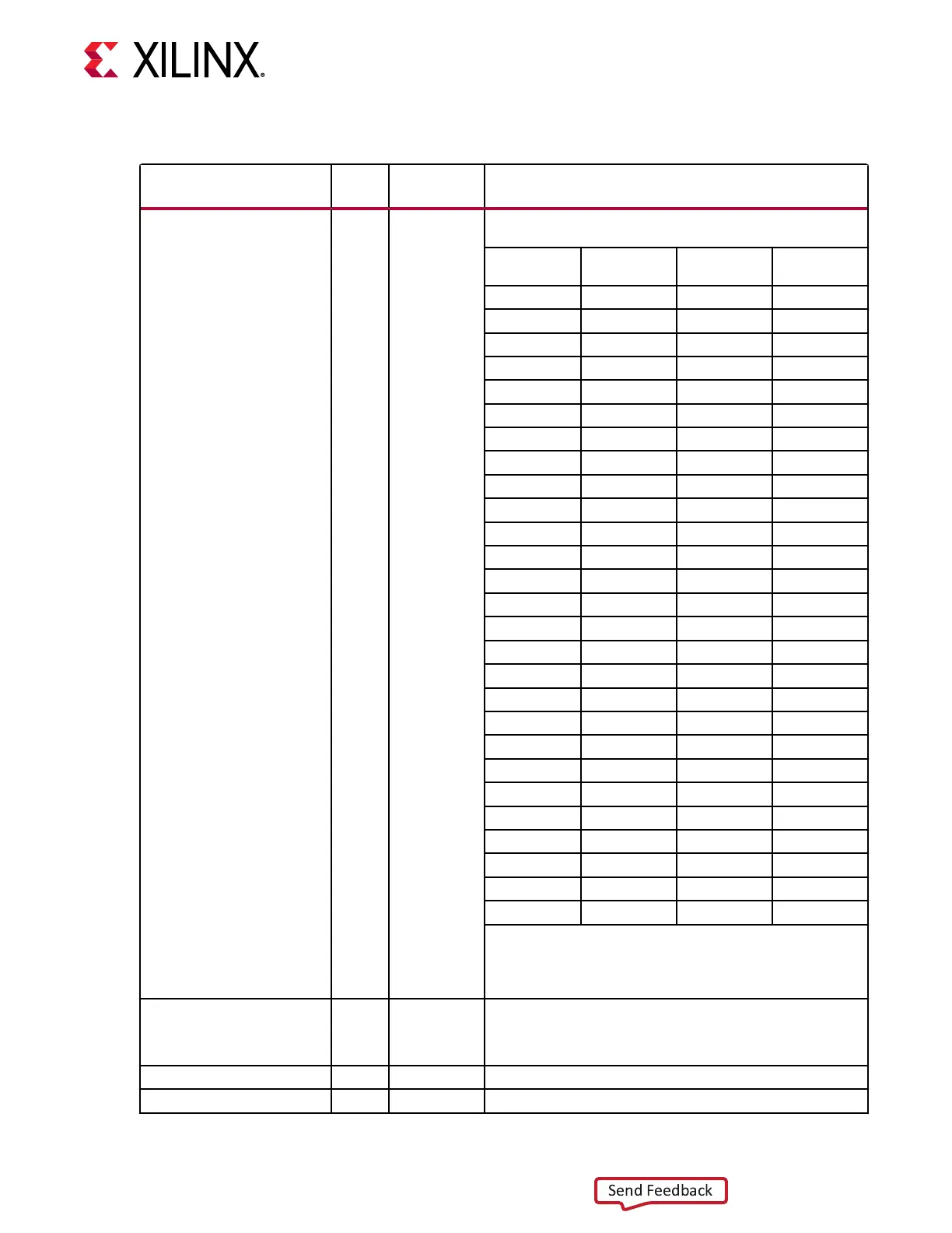
CH[0/1]_TXEMPPOST[4:0] Input Async Transmitter post-cursor TX pre-emphasis control for channel 0.
The default is user specified. All listed values (dB) are typical.
[4:0] dB (PAM4) dB (NRZ) Coefficient
Units
5’b00000
0.0 0.0 0
5’b00001
–0.3 –0.2 1
5’b00010
–0.7 –0.5 2
5’b00011
–1.1 –0.7 3
5’b00100
–1.5 –0.9 4
5’b00101
–1.9 –1.2 5
5’b00110
–2.3 –1.5 6
5’b00111
–2.7 –1.7 7
5’b01000
–3.2 –2.0 8
5’b01001
–3.7 –2.3 9
5’b01010
–4.2 –2.6 10
5’b01011
–4.8 –2.9 11
5’b01100
–5.4 –3.2 12
5’b01101
–6.0 –3.5 13
5’b01110
–6.7 –3.9 14
5’b01111
–7.5 –4.2 15
5’b10000
–8.3 –4.6 16
5’b10001
–9.2 –5.0 17
5’b10010
N/A –5.4 18
5’b10011
N/A –5.8 19
5’b10100
N/A –6.2 20
5’b10101
N/A –6.7 21
5’b10110
N/A –7.2 22
5’b10111
N/A –7.7 23
5’b11000
N/A –8.3 24
5’b11001
N/A –8.9 25
5’b11010
N/A –9.2 26
Notes:
1. The peak-to-peak differential voltage is defined when
TXEMPPRE = 5’b00000, and TXEMPPRE2 = 4’b0000.
Emphasis = 20log10(V
high
/V
low
) = |20log10(V
low
/V
high
)|.
CH[0/1]_GTMTXP
CH[0/1]_GTMTXN
Output
(pad)
TX Serial Clock Differential complements of one another forming a differential
transmit output pair. These ports represent the pads. The
locations of these ports must be constrained (see
Implementation) and brought to the top of the design.
CH[0/1]_TXCTLFIRDAT[5:0] Input Async Reserved. Use the recommended value from the Wizard
CH[0/1]_TXMUXDCDEXHOLD Input Async Reserved. Use the recommended value from the Wizard.
Chapter 3: Transmitter
UG581 (v1.0) January 4, 2019 www.xilinx.com
Virtex UltraScale+ GTM Transceivers 82
 Loading...

