7-7
SPEC
MAINTENANCE SPECIFICATIONS
Carburetor: mm (in)
Type BV26-20
I.D. mark 7CH00
7CH10 (For EF7200 SEA/AFR)
7HD00 (EF7000E/EF7200E/EF7200DE)
Bore size ø20
Main jet #105
Main air jet ø1.4 (0.055)
ø1.5 (0.059) (For EF7200 SEA/AFR)
Pilot air jet ø0.9 (0.053)
Pilot outlet ø0.9 (0.053)
Valve seat size ø1.8 (0.071)
Main nozzle 63C
65A (For EF7200 SEA/AFR)
Pilot jet #53.8
Pilot adjusting screw 2-1/2 turns out
2 turns out (For EF7200 SEA/AFR)
Throttle valve #120
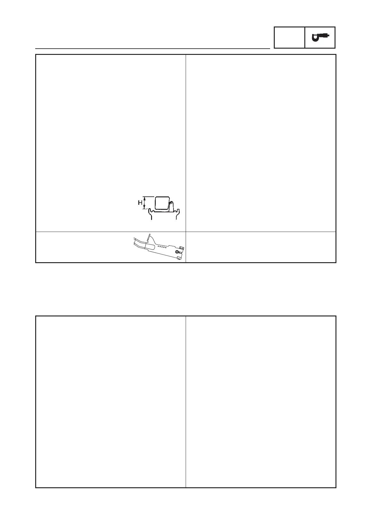
Float height “H” 14.9 (0.59)
Governor arm:
Tension spring attach hole* 2
4 (EF7200DE)
* Holes numbers are #1–#5 from right to left, when looking down the governor arm from the panel
side.
ELECTRICAL
Electrical:
Ignition system
Ignition timing at 3600 r/min BTDC 20° ± 3°
Spark plug type BPR4ES (NGK)
Gap mm (in) 0.7–0.8 (0.028–0.031)
Primary coil resistance (W ± 20 %) 0.6
Secondary coil resistance (kW ± 20 %) 12
Spark plug cap resistance kW 4.0–6.0
TCI unit air gap mm (in) 0.4–0.6 (0.0157–0.0236)
Minimum spark gap mm (in) 6.0 (0.236)
Charging coil resistance
Green/Red–Ground (W ± 20 %) 1.8
White–Ground (W ± 20 %) 2.0
Economy control system (EF7000E/EF7200E/EF7200DE)
Economy control voltage (DC)
(economy control unit) V 10–17
Solenoid voltage (DC) V 10.8–13.2
Solenoid resistance (W ± 5 %) 26
1
2
3
4
5