7-18
SPEC
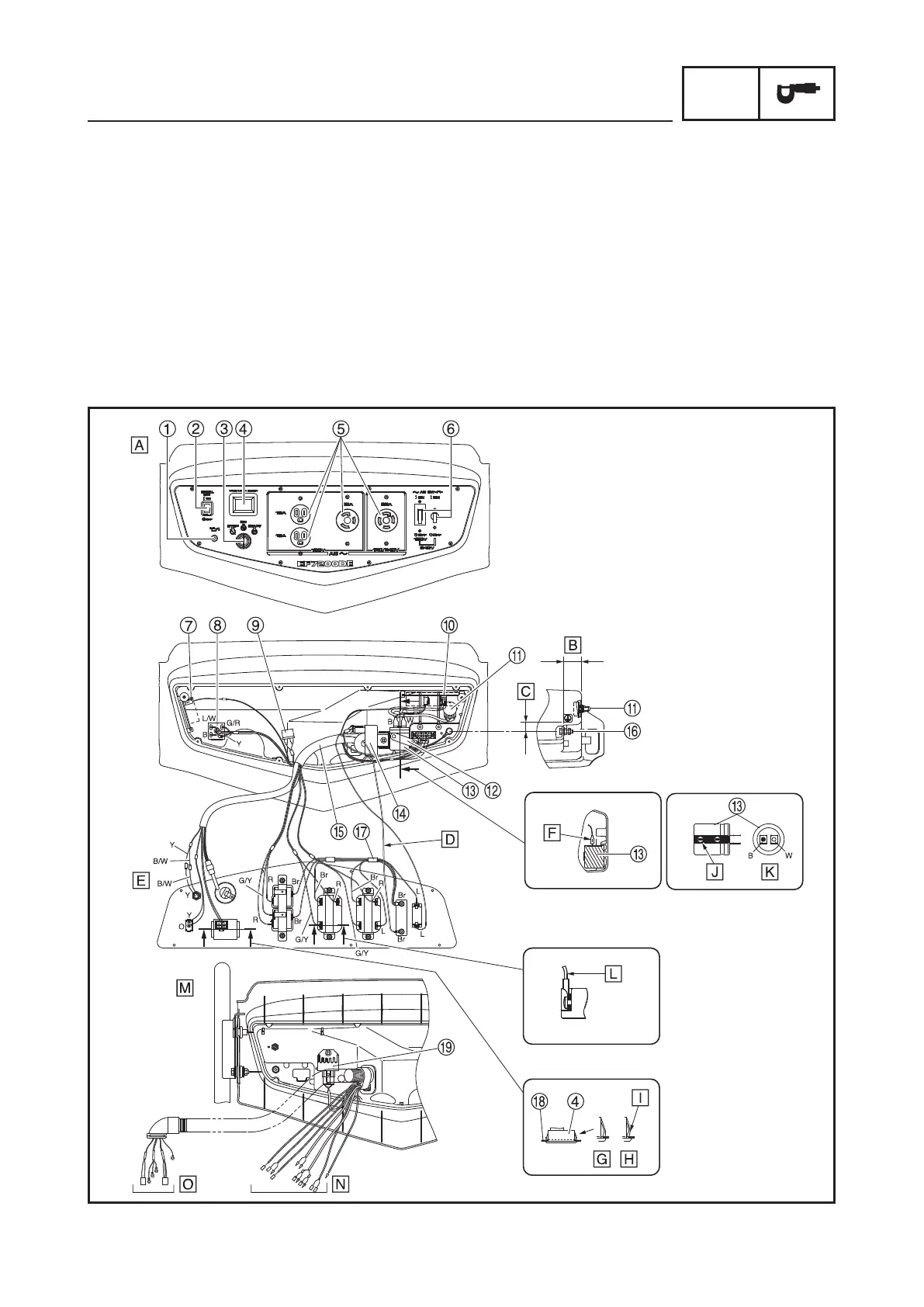
WIRE ROUTING DIAGRAM
1 Oil warning light
2 Economy control switch
3 Engine switch
4 Voltage/hour meter
5 AC receptacle
6 AC switch (N.F.B.)
7 Oil warning unit
8 Rectifier
9 Fuse
0 AVR
q Voltage adjuster
w Condenser holder
e Condenser
r Economy control unit
t Wire harness
y Ground (earth) terminal
u Sub-wire harness
i Panel cover
o Rectifier/regulator
A
Control box
B
32.6 mm (1.28 in)
C
16 mm (0.63 in)
D
Route the brown lead through
the coil of the economy control
unit.
E
Behind the control box panel
F
Connect the condenser lead
coupler as shown in the illus-
tration, paying attention to
polarity.
G
Pawls on voltage/hour meter
properly engaged
H
Pawls on voltage/hour meter
improperly engaged
I
Make sure that the pawls are
properly engaged on both
sides of the panel cover.
J
Negative side mark
CONTROL PANEL AND CONTROL BOX (Except for EF7200DE CAN)


 To Next Page