3-17
ENG
a
b
1
b
1
a
c
1
d
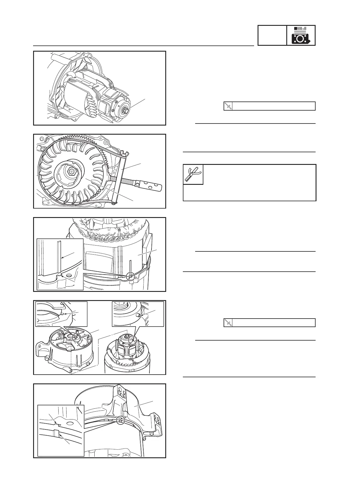
3. Install:
9 Stator assembly 1
9 Stator cover
TIP
Align the projection a on the stator assembly
1 with the slot b on the crankcase cover.
4. Install:
9 Rear frame 1
10 Nm (1.0 m · kgf, 7.2 ft · lbf)
TIP
9 Align the pin a on the rotor bearing with
the slot b on the rear frame.
9 Align the projection c on the stator assem-
bly with the slot d on the rear frame.
INSTALLING THE STATOR ASSEMBLY AND
ROTOR ASSEMBLY
1. Install:
9 Rotor assembly
2. Tighten:
9 Rotor assembly bolt 1
42 Nm (4.2 m · kgf, 30 ft · lbf)
TIP
Tighten the rotor assembly bolt 1 by attach-
ing the sheave holder 2 to hold the flywheel
3.
Primary clutch holder:
YS-01880-A
Sheave holder:
90890-01701
1
2
3
GENERATOR
 Loading...