3-22
ENG
PISTON, CAMSHAFT, CRANKCASE, AND
CRANKSHAFT
b
1
a
b
1
a
INSTALLING THE VALVE LIFTER,
BALANCER SHAFT, AND CAMSHAFT
1. Install:
9 Intake valve lifter
9 Exhaust valve lifter
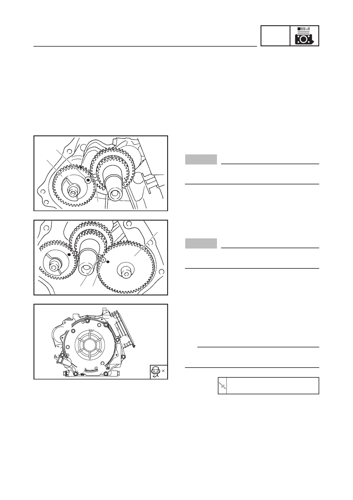
2. Install:
9 Balancer shaft 1
NOTICE
Be sure to align the balancer shaft 1 gear
mark a with the crankshaft gear mark b.
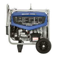
3. Install:
9 Camshaft 1
NOTICE
Be sure to align the camshaft 1 gear mark
a with the crankshaft gear mark b.
1
5
3
7
2
6
4
8
8
INSTALLING THE CRANKCASE COVER
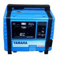
1. Install:
9 Crankcase cover
9 Crankcase cover bolts 1 to 8
TIP
Tighten the bolts to the specified torque in two
stages and in order from 1 to 8.
1st: 12 Nm (1.2 m · kgf, 8.7 ft · lbf)
2nd: 30 Nm (3.0 m · kgf, 22 ft · lbf)


 To Next Page