3-1
ENG
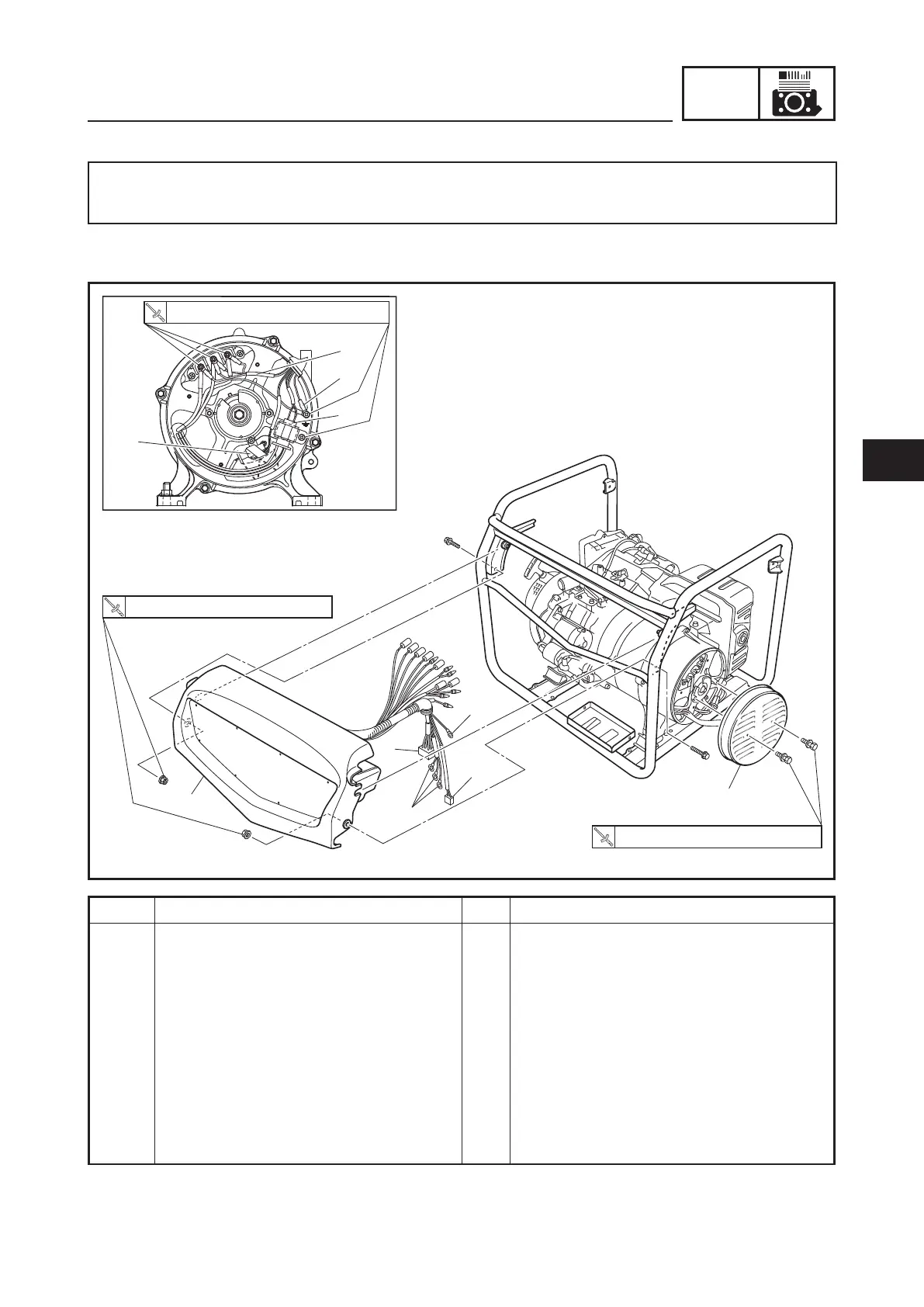
CONTROL BOX
1
2
3
4
5
6
5
6
3
4
3.8 Nm (0.38 m á kgf, 2.8 ft á lbf)
7 Nm (0.7 m á kgf, 5.1 ft á lbf)
7 Nm (0.7 m á kgf, 5.1 ft á lbf)
Order Job/Parts to remove Q’ty Remarks
Removing the control box Remove the parts in the order listed.
Negative battery lead Disconnect.
Carrier frame Refer to “HANDLE AND WHEELS (FOR
EF7200DE CAN)” on 3-23.
Fuel tank Refer to “FUEL TANK, CANISTER” on 3-7.
1 Generator cover 1
2 Control box 1
3 Ground lead 1
4 Stator assembly (main coil) lead 3
5 Stator assembly (sub coil) coupler 1
6 Exciter field coil coupler 1
ENGINE
For complete information about procedures for engine maintenance, it is necessary to refer to
the MZ SERIES ENGINE SERVICE MANUAL 7VB-F8197-E0.
CONTROL BOX
EF7200DE
3


 To Next Page