POWR
Power unit
5-47
6D81G11
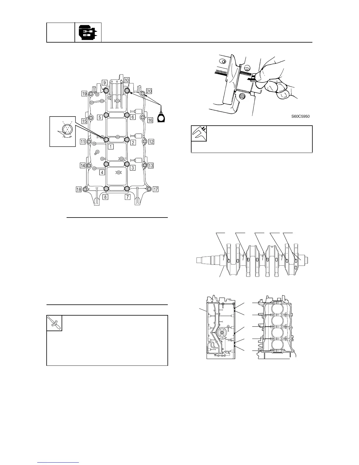
7. Tighten the crankcase bolts to the speci-
fied torques in two stages and in the
sequence shown.
NOTE:
• Do not move the crankshaft until the crank-
shaft journal oil clearance measurement
has been completed.
• Tighten the M10 bolts to 19 N·m (1.9 kgf·m,
14.0 ft·lb) first, and then tighten the M8
bolts to 14 N·m (1.4 kgf·m, 10.3 ft·lb).
• Make a mark
b
on the M10 bolts and the
crankcase, and then tighten the bolts 60°
from the mark.
• Tighten the M8 bolts to 28 N·m (2.8 kgf·m,
20.7 ft·lb).
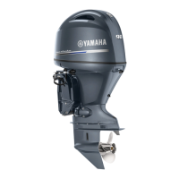
8. Remove the crankcase, and then mea-
sure the width of the compressed Plasti-
gauge (PG-1) on each crankshaft
journal. Replace the main bearing if out
of specification.
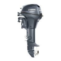
Selecting the main bearing
1. When replacing the main bearing, select
the suitable bearing as follows.
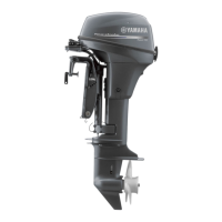
2. Check the crankshaft journal mark on the
crankshaft
1
and the cylinder block mark
on the cylinder block
2
.
3. Subtract crankshaft journal diameters
#1–#5 from cylinder block journal inside
diameters #1–#5.
T
R
.
.
Crankcase bolt (M10):
1st: 19 N·m (1.9 kgf·m, 14.0 ft·lb)
2nd: 60°
Crankcase bolt (M8):
1st: 14 N·m (1.4 kgf·m, 10.3 ft·lb)
2nd: 28 N·m (2.8 kgf·m, 20.7 ft·lb)
S6D85600
60˚
b
E
Crankshaft journal oil clearance:
0.024–0.044 mm
(0.0009–0.0017 in)
(#1) (#2) (#3)
(#4)
(#5)
S60C5A40
1
#1
#2
#3
#4
#5
S60C5A50
2