6D81G11
8-8
1
2
3
4
5
6
7
8
9
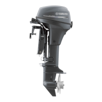
Checking the ECM
1. Disconnect an ignition coil coupler.
2. Connect the test harness (2 pins) to the
ignition coil.
3. Measure the ECM output peak voltage. If
below specification, measure the pulser
coil output peak voltage. Replace the
ECM if the output peak voltage of the
pulser coil is above specification.
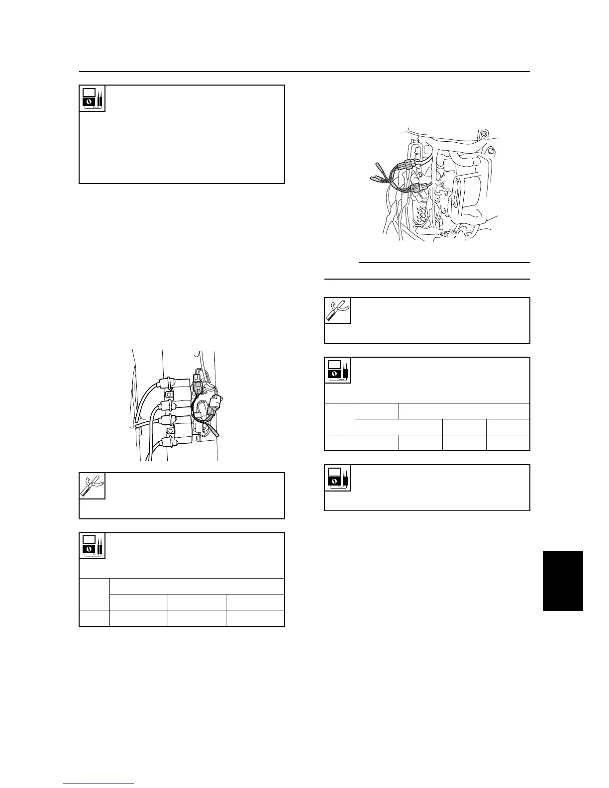
Checking the pulser coils
1. Remove the junction box cover. Discon-
nect the pulser coil coupler.
2. Connect the test harness (3 pins) to the
pulser coil.
3. Measure the pulser coil output peak volt-
age. Replace the stator assembly if
below specification.
NOTE:
Do not loosen the pulser coil screw.
Checking the sensor assembly
1. Measure the ambient temperature.
Ignition coil resistance:
Primary coil:
Red (R) – Black/white (B/W)
1.53–2.07
Ω
at 20 °C (68 °F)
Secondary coil:
12.495–16.905 k
Ω
at
20 °C (68 °F)
Digital multimeter: YU-34899-A
Peak volt meter adapter: YU-39991
Test harness (2 pins): YB-06792
ECM output peak voltage:
Black/red (B/R) – Ground
Black/white (B/W) – Ground
r/min
Loaded
Cranking 1,500 3,500
DC V 210 290 290
S6D88070
Digital multimeter: YU-34899-A
Peak volt meter adapter: YU-39991
Test harness (3 pins): YB-06791
Pulser coil output peak voltage:
White/red (W/R) – Black (B)
White/black (W/B) – Black (B)
r/min
Unloaded
Loaded
Cranking 1,500 3,500
DC V 3.6 3.4 18.2 34.3
Pulser coil resistance
(reference data):
459–561
Ω
S6D88080
Ignition and ignition control system