ELEC
Electrical systems
– +
8-17
6D81G11
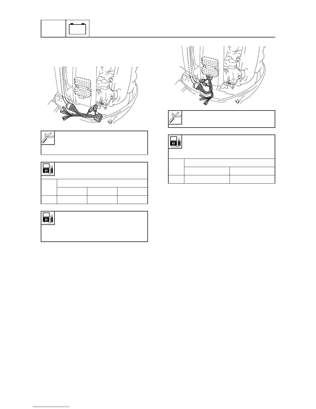
3. Measure the stator coil output peak volt-
age. Replace the stator coil if below
specification.
Checking the Rectifier Regulator
1. Disconnect the stator coil coupler.
2. Connect the test harness (6 pins)
between the Rectifier Regulator and sta-
tor coil coupler.
3. Disconnect the test harness coupler and
then measure the Rectifier Regulator
output peak voltage at the coupler
1
. If
below specification, measure the stator
coil output peak voltage. Replace the
Rectifier Regulator if the output peak
voltage of the stator coil is above specifi-
cation.
Digital multimeter: YU-34899-A
Peak volt meter adapter: YU-39991
Test harness (6 pins): YB-06848
Stator coil output peak voltage:
White (W) – White (W)
r/min
Unloaded
Cranking 1,500 3,500
DC V 12.4 45.3 98.3
Stator coil resistance
(reference data):
White (W) – White (W)
0.24–0.36
Ω
at 20 °C (68 °F)
S6D88140
Digital multimeter: YU-34899-A
Test harness (6 pins): YB-06848
Rectifier Regulator output peak
voltage:
Red (R) – Ground
r/min
Unloaded
1,500 3,500
DC V 13.0 13.0
S6D88150
1