6D81G11
8-16
1
2
3
4
5
6
7
8
9
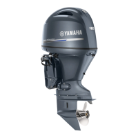
Checking the brushes
1. Measure the brush length. Replace the
brush assembly if below specification.
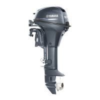
2. Check the brush holder assembly for
continuity. Replace if out of specification.
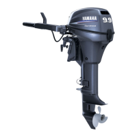
Checking the magnet switch
1. Connect the tester leads between the
magnet switch terminals as shown.
2. Connect the positive battery lead to the
brown (Br) lead.
3. Connect the negative battery lead to the
starter motor body.
CAUTION:
Do not connect the battery for more than
one second, otherwise the magnet switch
can be damaged.
4. Check that there is continuity between
the magnet switch terminals. Replace if
there is no continuity.
5. Check that there is no continuity after the
negative battery terminal is removed.
Replace if there is continuity.
NOTE:
The starter motor pinion should be pushed
out while the magnet switch is on.
Checking the starter motor operation
1. Check the operation of the starter motor
after installing it onto the power unit.
Charging system
8
Checking the stator coil
1. Disconnect the stator coil coupler.
2. Connect the test harness (6 pins) to the
stator coil coupler.
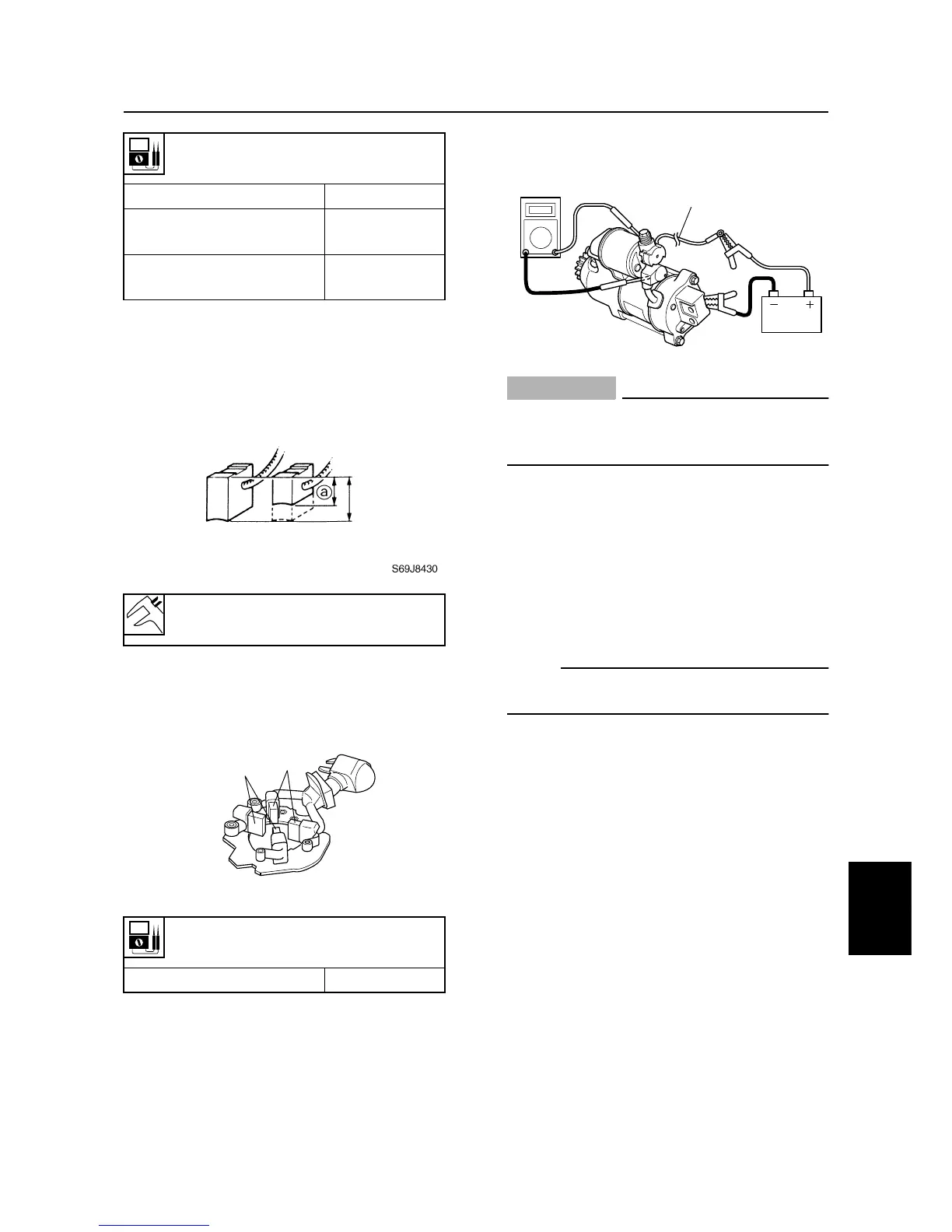
Armature continuity
Commutator segments
b
Continuity
Segment –
Armature core
c
No continuity
Segment –
Armature shaft
d
No continuity
Brush length wear limit
a
:
9.5 mm (0.37 in)
Brush continuity
Brush
1
– Brush
2
No continuity
S69J8440
1
2
S6D88130
Br
Starter motor / Charging system