6D81G11
7-40
1
2
3
4
5
6
7
8
9
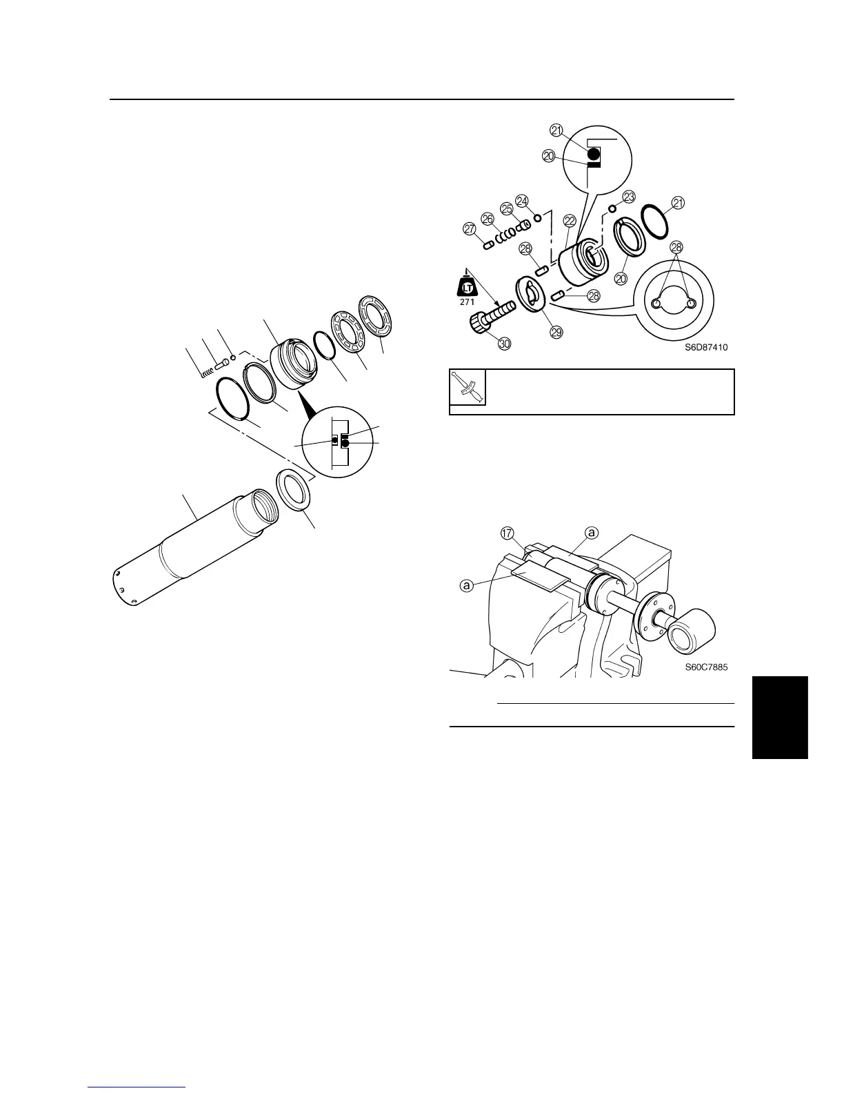
6. Install the new O-rings
9
and
0
, and
backup ring
A
onto the trim piston
B
.
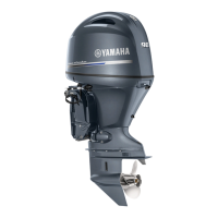
7. Install the balls
C
, valves
D
, and springs
E
into the trim piston, and then install the
washer
F
and trim piston to the tilt cylin-
der
G
.
8. Install the filter
H
and washer
I
to the
trim piston.
9. Install the backup ring
J
and new O-ring
K
to the tilt piston
L
.
10. Install balls
M
and
N
, valves
O
, springs
P
, pins
Q
, dowels
R
, and washer
S
into the tilt piston.
11. Hold the tilt ram end in a vise using alu-
minum plates on both sides.
12. Install the tilt piston to the tilt ram by
installing the bolt
T
, then tightening it to
the specified torque.
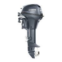
13. Install the tilt ram into the tilt cylinder.
14. Hold the tilt cylinder
G
in a vise using
aluminum plates
a
on both sides.
NOTE:
Place the tilt cylinder in the vise horizontally.
S60C7875
I
A
B
C
D
E
F
G
H
9
0
A
9
0
Tilt piston bolt
T
:
85 N·m (8.5 kgf·m, 62.7 ft·lb)
Tilt cylinder and trim cylinder