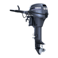
Wiring diagram
F90TR
1 Ignition coil
2 Spark plug
3 Power trim and tilt switch (tiller handle)
(optional)
4 Power trim and tilt switch (bottom cowling)
5 Battery
6 Cooling water temperature sensor
7 Starter motor
8 Fuse (30 A)
9 Fuse (20 A)
0 Neutral switch (optional)
A Starter relay
B Power trim and tilt relay
C Trim sensor
D Power trim and tilt motor
E Electric fuel pump
F Main and fuel pump relay
G Diode
H Oil pressure switch
I Pulser coil
J Stator coil
K Rectifier Regulator
L ECM
M Throttle position sensor
N Shift position switch
O Sensor assembly
P Fuel injector
Q Idle speed control
R Variable trolling RPM switch (optional)
È To warning indicator/trim meter
É To remote control box/switch panel
Ê To personal computer for diagnosis
Ë To diagnostic flash indicator (special service
tool)
Ì To Variable trolling RPM switch
Color code
B: Black
Br : Brown
G: Green
L: Blue
Lg : Light green
O : Orange
P: Pink
R: Red
Sb : Sky blue
W: White
Y : Yellow
B/R : Black/red
B/W : Black/white
B/Y : Black/yellow
Br/W : Brown/white
G/B : Green/black
G/R : Green/red
G/Y : Green/yellow
L/G : Blue/green
L/W : Blue/white
L/Y : Blue/yellow
O/W : Orange/white
P/B : Pink/black
P/G : Pink/green
P/W : Pink/white
Pu/B : Purple/black
Pu/R : Purple/red
R/B : Red/black
R/Y : Red/yellow
W/B : White/black
W/L : White/blue
W/R : White/red



 To Next Page