6C13G11
5-26
1
2
3
4
5
6
7
8
9
NOTE:
Apply engine oil to the surface of the new
valve guide.
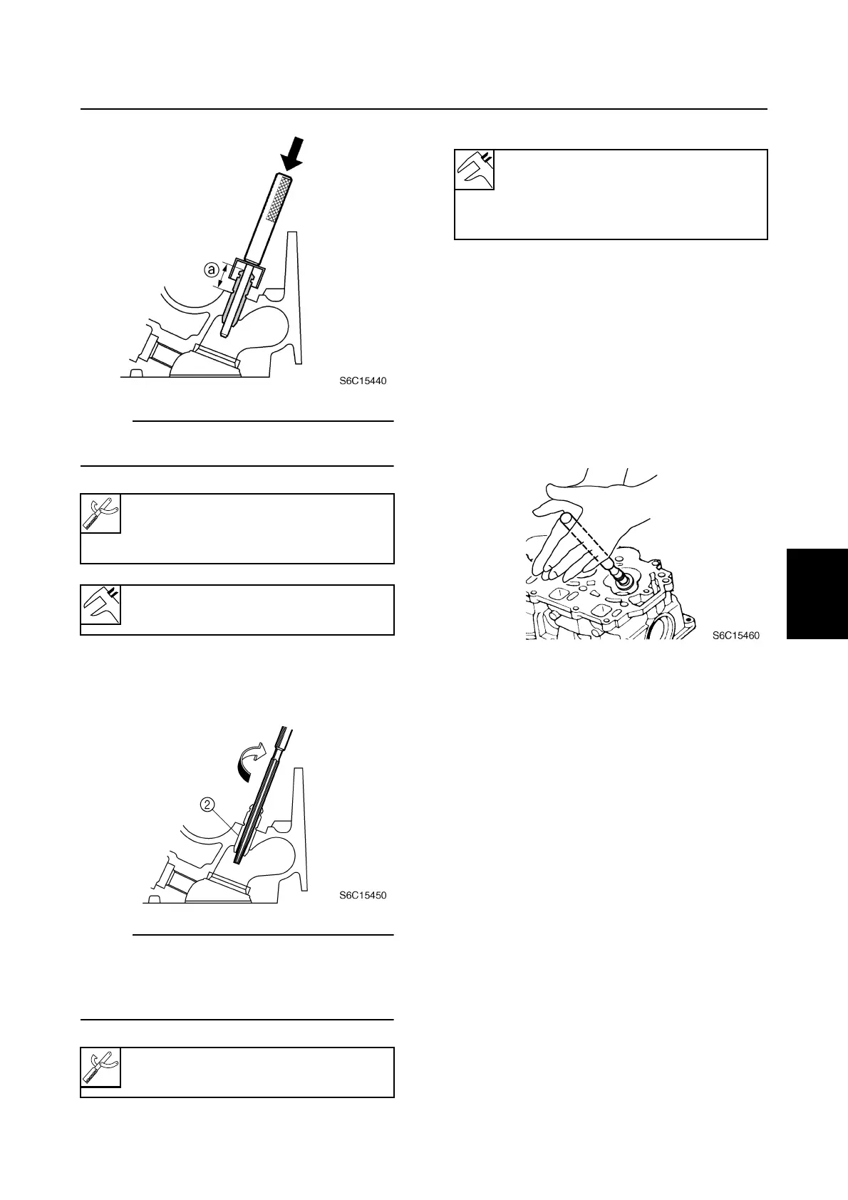
3. Insert the special service tool into the
valve guide
2
, and then ream the valve
guide.
NOTE:
• Turn the valve guide reamer clockwise to
ream the valve guide.
• Do not turn the reamer counterclockwise
when removing the reamer.
4. Measure the valve guide inside diameter.
Checking the valve seat
1. Eliminate carbon deposits from the valve
with a scraper.
2. Apply a thin, even layer of Mechanic’s
blueing dye (Dykem) onto the valve seat.
3. Lap the valve slowly on the valve seat
with a valve lapper (commercially avail-
able) as shown.
Valve guide remover/installer:
90890-06801
Valve guide installer: 90890-06810
Valve guide position
a
:
16.5
±
0.2 mm (0.650
±
0.008 in)
Valve guide reamer: 90890-06804
Valve guide inside diameter:
Intake and exhaust:
5.500–5.512 mm
(0.2165–0.2170 in)
Cylinder head