ELEC
Electrical systems
– +
8-9
6C13G11
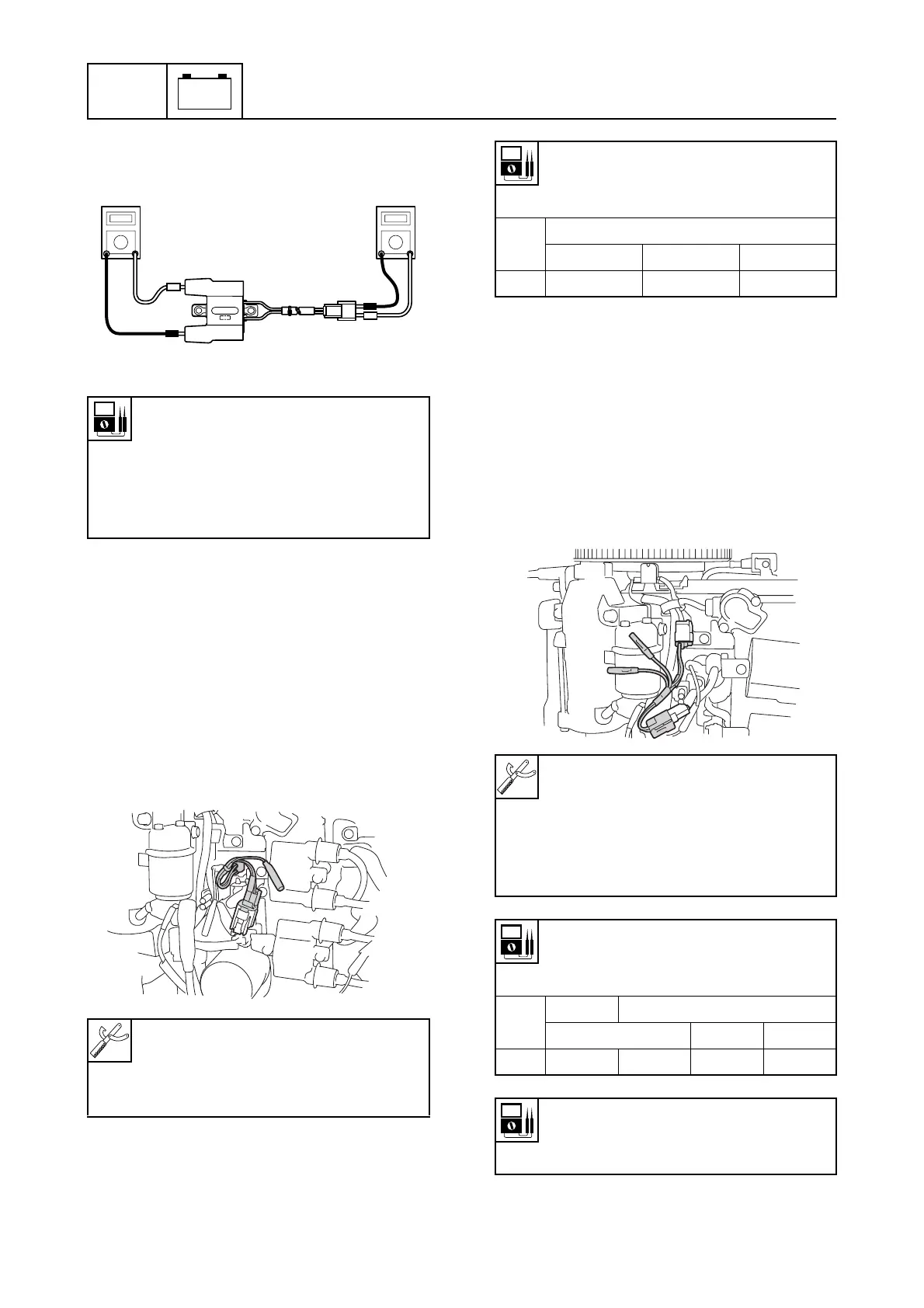
3. Measure the ignition coil resistance.
Replace if out of specification.
Checking the ECM
1. Disconnect an ignition coil coupler.
2. Connect the test harness (2 pins) to the
ignition coil.
3. Measure the ECM output peak voltage. If
below specification, measure the pulser
coil output peak voltage. Replace the
ECM if the output peak voltage of the
pulser coil is above specification.
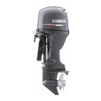
Checking the pulser coil
1. Remove the flywheel magnet cover and
disconnect the pulser coil coupler.
2. Connect the test harness (2 pins) to the
pulser coil.
3. Measure the pulser coil output peak volt-
age. Replace the pulser coil if below
specification.
Ignition coil resistance:
Primary coil:
Red (R) – Black/white (B/W)
1.53–2.07
Ω
at 20 °C (68 °F)
Secondary coil:
12.50–16.91 k
Ω
at 20 °C (68 °F)
Digital circuit tester: 90890-03174
Peak voltage adapter B:
90890-03172
Test harness (2 pins): 90890-06792
S63P8100
S6C18050
ECM output peak voltage:
Black/red (B/R) – Ground
Black/white (B/W) – Ground
r/min
Loaded
Cranking 1,500 3,500
DC V 240 290 300
Digital circuit tester: 90890-03174
Peak voltage adapter B:
90890-03172
Test harness (2 pins):
New: 90890-06867
Current: 90890-06767
Pulser coil output peak voltage:
White/red (W/R) –
White/black (W/B)
r/min
Unloaded
Loaded
Cranking 1,500 3,500
DC V 7.9 7.2 20.7 32.0
Pulser coil resistance
(reference data):
396–594
Ω
S6C18060