6C13G11
8-20
1
2
3
4
5
6
7
8
9
Charging system
8
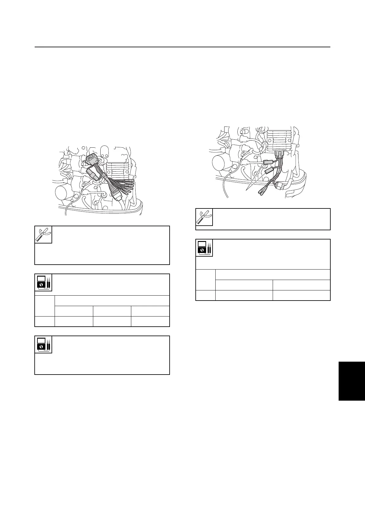
Checking the stator coil
1. Disconnect the stator coil coupler.
2. Connect the test harness (6 pins) to the
stator coil coupler.
3. Measure the stator coil output peak volt-
age. Replace the stator coil if below
specification.
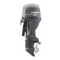
Checking the Rectifier Regulator
1. Disconnect the stator coil coupler.
2. Connect the test harness (6 pins)
between the Rectifier Regulator and sta-
tor coil coupler.
3. Disconnect the test harness coupler
1
,
and then measure the Rectifier Regulator
output peak voltage at the coupler. If
below specification, measure the stator
coil output peak voltage. Replace the
Rectifier Regulator if the output peak
voltage of the stator coil is above specifi-
cation.
Digital circuit tester: 90890-03174
Peak voltage adapter B:
90890-03172
Test harness (6 pins): 90890-06848
Stator coil output peak voltage:
White (W) – White (W)
r/min
Unloaded
Cranking 1,500 3,500
DC V 13.2 42.2 96.6
Stator coil resistance
(reference data):
White (W) – White (W)
0.52–0.63
Ω
at 20 °C (68 °F)
S6C18150
Digital circuit tester: 90890-03174
Test harness (6 pins): 90890-06848
Rectifier Regulator output peak
voltage:
Red (R) – Black (B)
r/min
Unloaded
1,500 3,500
DC V 13.0 13.0
S6C18140
1
Starter motor / Charging system