6C13G11
5-4
1
2
3
4
5
6
7
8
9
Checking the valve clearance
CAUTION:
Do not turn the flywheel magnet counter-
clockwise, otherwise the valve system
may be damaged.
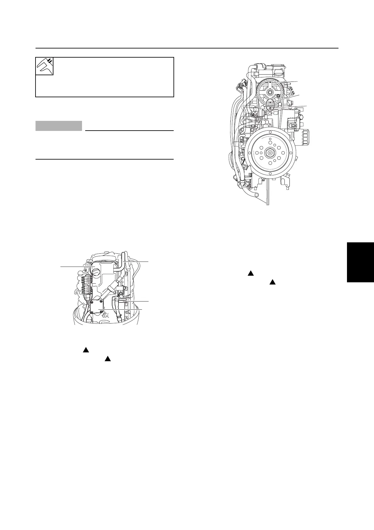
1. Remove the flywheel magnet cover, and
then remove the blowby hose
1
.
2. Remove the fuel pump
2
and fuel filter
3
.
3. Disconnect the spark plug caps and
remove the spark plugs and cylinder
head cover
4
.
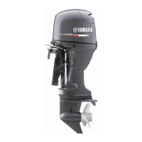
4. Turn the flywheel magnet clockwise and
align the “ 1” mark
a
on the driven
sprocket with the “” mark
b
on the cyl-
inder head.
5. Check the intake valve clearance for cyl-
inders #1 and #2, and the exhaust valve
clearance for cylinders #1 and #3. Adjust
if out of specification.
6. Turn the flywheel magnet clockwise and
align the “ 4” mark
c
on the driven
sprocket with the “” mark
b
on the cyl-
inder head.
Relief valve opening pressure
(reference data):
350–450 kPa
(3.5–4.5 kgf/cm
2
, 50.8–62.3 psi)
S6C15130
1
3
4
2
S6C15140
c
b
a
Power unit