POWR
Power unit
5-5
6C13G11
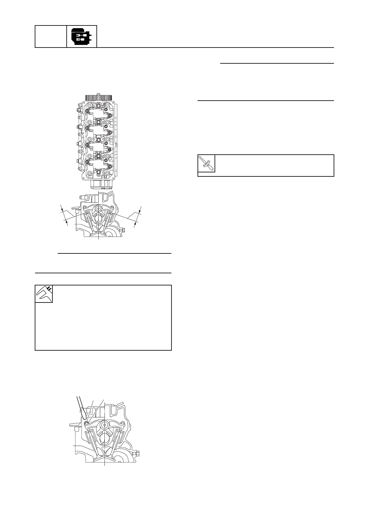
7. Check the intake valve clearance for cyl-
inders #3 and #4, and the exhaust valve
clearance for cylinders #2 and #4. Adjust
if out of specification.
NOTE:
Check the valve clearance when the engine
is cold.
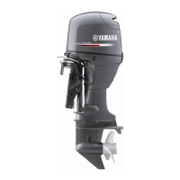
8. Loosen the rocker arm locknut
5
, and
then turn the adjusting screw
6
until the
specified valve clearance is obtained.
NOTE:
• To decrease the valve clearance, turn the
adjusting screw clockwise.
• To increase the valve clearance, turn the
adjusting screw counterclockwise.
9. Tighten the rocker arm locknut to the
specified torque, and then check the
valve clearance again. Adjust if neces-
sary.
10. Install the cylinder head cover, fuel
pump, fuel filter, spark plugs, spark plug
caps, blowby hose, and flywheel magnet
cover.
Valve clearance (cold):
Intake
d
:
0.20
±
0.05 mm
(0.008
±
0.002 in)
Exhaust
e
:
0.30
±
0.05 mm
(0.012
±
0.002 in)
S6C15150
#4
#3
#2
EX IN
#1
d
e
6
5
S6C15160
Rocker arm locknut
5
:
14 N·m (1.4 kgf·m, 10.3 ft·lb)