6C13G11
8-12
1
2
3
4
5
6
7
8
9
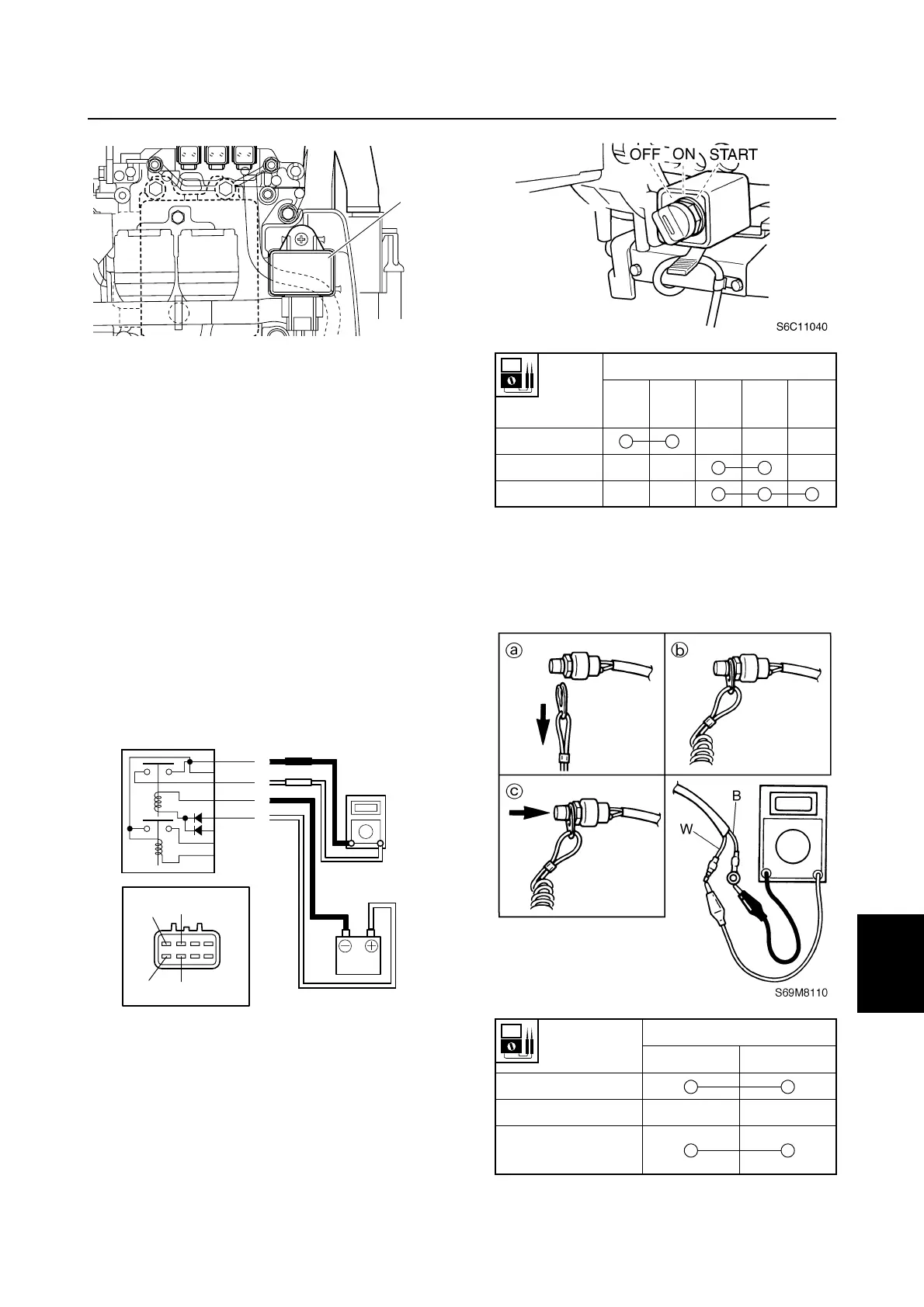
2. Connect the digital circuit tester leads to
the relay terminals
2
and
3
.
3. Connect the positive battery terminal to
the main and fuel pump relay terminal
4
.
4. Connect the negative battery terminal to
the main and fuel pump relay terminal
5
.
5. Check for continuity between the relay
terminals. Replace if there is no continu-
ity.
6. Check that there is no continuity between
the relay terminals after disconnecting a
battery terminal from the relay terminal
4
or
5
. Replace if there is continuity.
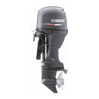
Checking the engine start switch
(tiller handle model)
1. Check the engine start switch for continu-
ity. Replace if there is no continuity.
Checking the engine stop lanyard
switch (tiller handle model)
1. Check the engine stop lanyard switch for
continuity. Replace if out of specification.
1
S6C18090
S6D88100
4
5
2
3
4
5
2
3
Switch
position
Lead color
White
(W)
Black
(B)
Red
(R)
Pink
(P)
Brown
(Br)
Off
On
Start
Switch
position
Lead color
White (W) Black (B)
Clip removed
a
Clip installed b
Engine stop
button pushed c
Ignition and ignition control system