6C13G11
5-46
1
2
3
4
5
6
7
8
9
Assembling the power unit
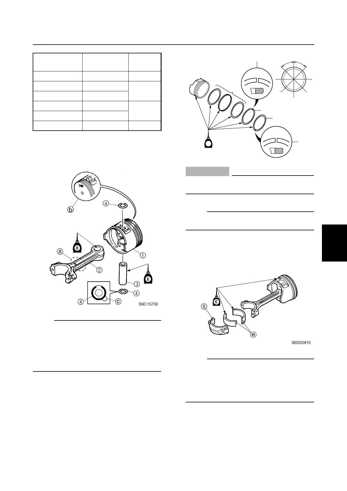
1. Assemble the piston
1
, connecting rod
2
, piston pin
3
, and piston pin clips
4
.
NOTE:
• Face the embossed “Y” mark
a
on the
connecting rod in the same direction as the
“UP” mark
b
on the piston.
• Always use new piston pin clips, and do not
allow the piston pin clip end to align with the
piston pin slot
c
.
2. Install the oil ring
5
, second ring
6
, and
top ring
7
onto each piston with the “T”
marks
d
of the second ring and the top
ring facing upward.
3. Offset the piston ring end gaps as
shown.
CAUTION:
Do not scratch the pistons or break the
piston rings.
NOTE:
After installing the piston rings, check that
they move smoothly.
4. Install the upper bearing into the con-
necting rod and the lower bearing into
the connecting rod cap
8
.
NOTE:
• Install the connecting rod bearings in their
original positions.
• Insert the projection
e
of each bearing into
the slots in the connecting rod cap and con-
necting rod.
Cylinder body
mark
Crankshaft
journal mark
Bearing
color
AAYellow
AB
Red
BA
BB
Pink
CA
C B Green
S6D55900
T
UP
#1,#4
#2
#5
#3
45˚ 45˚
T
63P
UP
#1
#2
#5
#4
#3
E
5
6
7
d
d
Cylinder block