Setup
Reference Manual
215
• Scene store operations
• DIMMER (MONITOR screen) operations
• Panel LED and display brightness (SETUP screen) operations
• Master mute group operations
3 CASCADE COMM PORT buttons
Specify the communication port used for transmitting and receiving link information
when operations such as cue and scene store/recall are linked between cascade-
connected QL series consoles.
• NONE.....................No link operation
• MIDI........................Use MIDI port
• SLOT1....................Use SLOT1
4 Tabs
Enable you to switch between items.
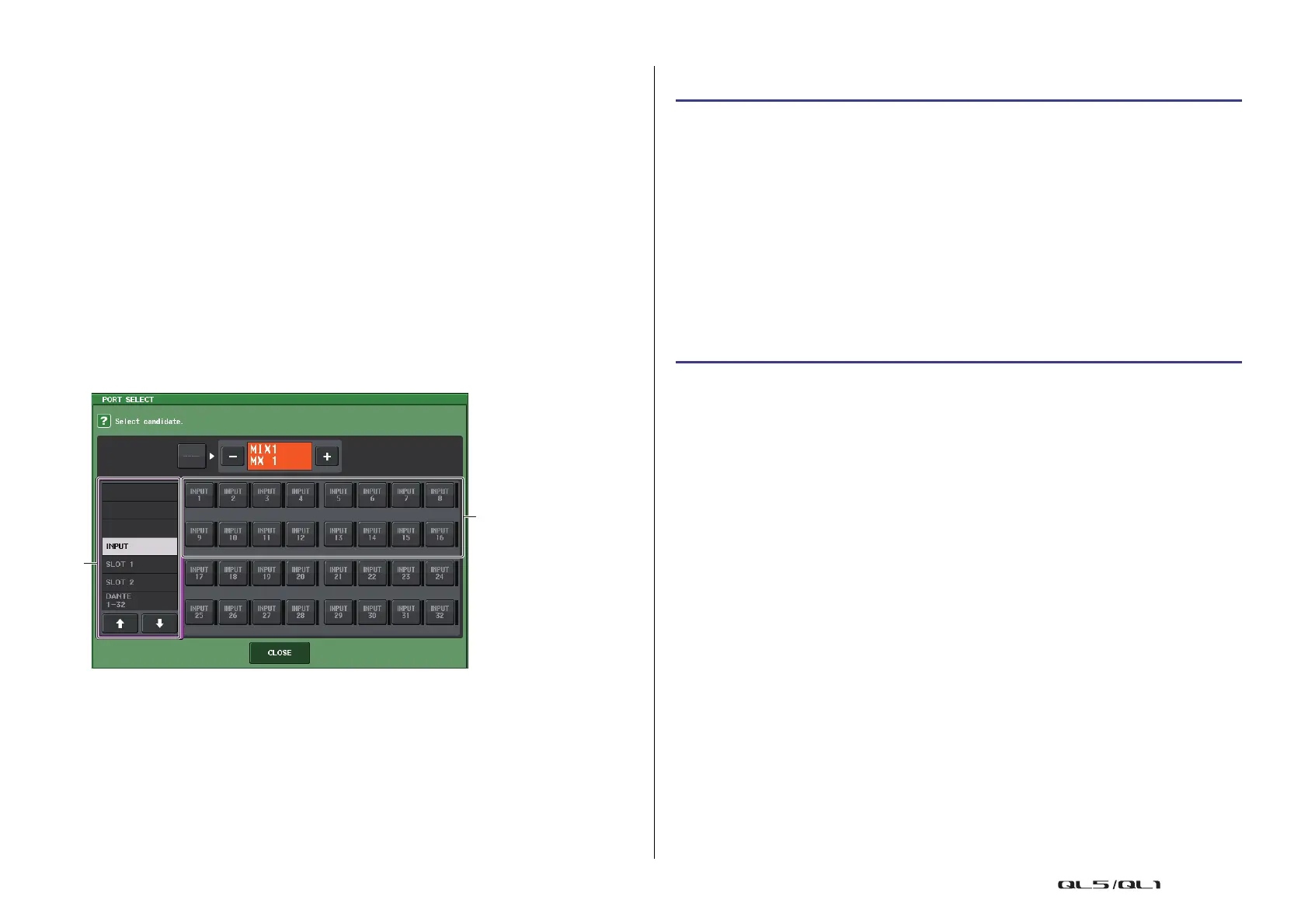
PORT SELECT window
Press the OUT PATCH button to open this window.
1 Category select list
Selects the port (slot 1–2) that will be shown on the screen.
2 Port select buttons
Within the specified slot, these buttons select the ports that will be patched.
Operations on the cascade master QL unit
NOTE
• You can assign the same input port to two or more buses.
• Control signals for the cascade link and MIDI messages cannot share the same port. If you select
a port that is already specified for transmission/reception of MIDI messages, a dialog box will ask
whether it is OK to cancel the existing settings.
STEP
1. In the Function Access Area, press the SETUP button.
2. In the SYSTEM SETUP field of the SETUP screen, press the CASCADE button.
3. In the CASCADE window, press the CASCADE IN PATCH tab.
4. In the CASCADE IN PATCH page, press the IN PATCH button for the bus to which you
want to assign the port.
5. In the PORT SELECT screen, use the category select list and the port select buttons
to select the slot and input ports that you want to assign, and then press the CLOSE
button.
6. As described in step 6 of “Operations on a cascade slave QL unit” on page 214, in
the CASCADE LINK PORT field, select the port that will transmit and receive control
signals for cascade link.
7. As described in step 7 of “Operations on a cascade slave QL unit” on page 214, in
the CASCADE COMM LINK field, select the same item as the cascade slave.

 Loading...


