OUTPUT channels
Reference Manual
49
Sending signals from MIX channels and STEREO/
MONO channels to MATRIX buses
You can send a signal from a MIX or STEREO/MONO channel to MATRIX buses 1–8 in the
following two ways.
Using the SELECTED CHANNEL section
With this method, you use the [TOUCH AND TURN] knob to adjust the send levels to the
MATRIX buses. This method allows you to simultaneously control the signals sent from a
specific MIX, STEREO (L/R), or MONO (C) channel to all MATRIX buses.
Using the faders (SENDS ON FADER mode)
With this method, you switch the QL series unit to SENDS ON FADER mode, and use the
faders on the top panel to adjust the level of signals sent to the MATRIX buses. When using
this method, signals sent from MIX and STEREO/MONO channels to a specific MIX/MATRIX
bus can be adjusted simultaneously.
Using the SELECTED CHANNEL section
Use the [TOUCH AND TURN] knob to adjust the send level of signals sent from the desired
MIX, STEREO (L/R) or MONO (C) channel to all MATRIX buses.
NOTE
• You can also use the [SEL] key in the MASTER section to directly select the STEREO/MONO
channels.
• If you want to monitor the signal being sent to a specific MATRIX bus, use the Bank Select keys
in the Fader Bank section to access the corresponding MIX/MATRIX channel, and then press the
appropriate [CUE] key in the Channel Strip section.
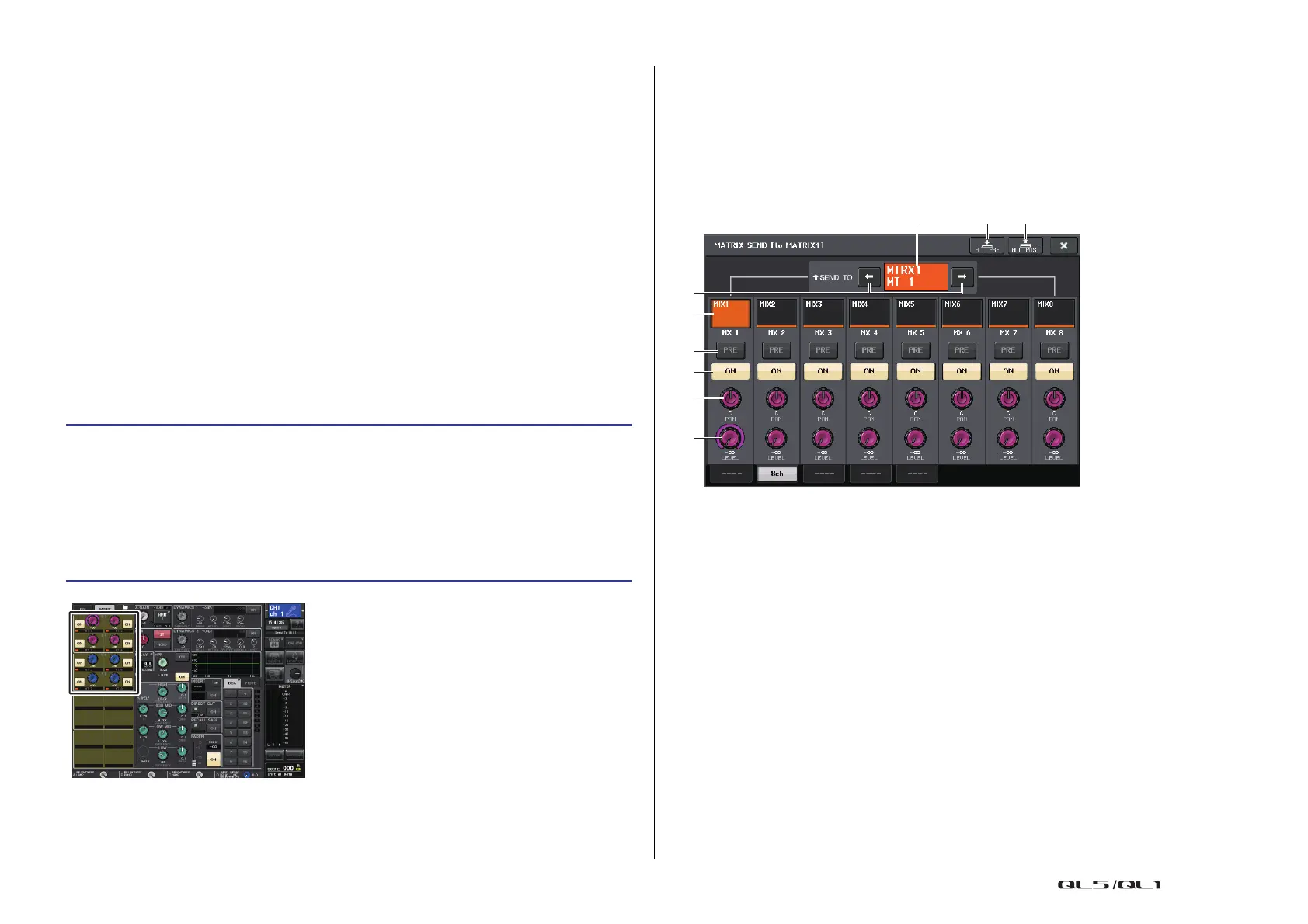
MATRIX SEND screen
1 ALL PRE button
Sets the send point to PRE. (The send point is the point at which signals are sent from
all send-source channels — including the input and output channels — to the selected
send destination.)
2 ALL POST button
Sets the send point to POST. (The send point is the point at which signals are sent from
all send-source channels — including the input and output channels — to the selected
send destination.)
3 Send destination indicator
Indicates the currently-selected send destination.
4 Send destination select buttons
Select MIX/MATRIX buses as the send destination.
5 Channel select button
Selects the send-source channel that you wish to control. The current channel icon,
number, and color appear on the button, and the channel name appears below the
button.
STEP
1. Assign an output port to the MATRIX bus to which you want to send signals, and
connect an external device.
2. Use the Bank Select keys in the Fader Bank section and the [SEL] keys on the top
panel to select the channels that will send signals to the MATRIX buses.
3. In the SELECTED CHANNEL VIEW screen, turn on the TO MATRIX SEND ON/OFF
button for the send-destination MATRIX bus.
4. Use the [TOUCH AND TURN] knob to adjust the send levels to the MATRIX buses.
SELECTED CHANNEL VIEW screen

 Loading...


