SELECTED CHANNEL section
Reference Manual
6
SELECTED CHANNEL section
The SELECTED CHANNEL section located at the right of the display corresponds to a
channel module of a conventional analog mixer, and allows you to use the knobs on the panel
to set all the major parameters of the currently-selected channel.
Operations in this section will affect the channel that was most recently selected by its [SEL]
key. If you have assigned an ST IN channel or STEREO channel to a single channel strip,
either the L or the R channel will be selected, and the major parameters for L and R channels
will be linked.
Operations in the SELECTED CHANNEL section
Follow the steps below to perform operations in the SELECTED CHANNEL section.
NOTE
• The number and name of the currently-selected
channel is shown in the channel select field located in
the Function Access Area of the touch screen.
• If an ST IN channel or STEREO channel has been
assigned to a single channel strip, you can switch
between L and R by repeatedly pressing the same
[SEL] key.
• You can also switch channels by pressing the channel select field located in the Function Access
Area. Press the left side of the field to select the preceding channel. Press the right side of the
field to select the next channel.
• If you have turned on the option “POPUP APPEARS WHEN KNOB(S) PRESSED” on the
PREFERENCE tab (accessed by pressing the SETUP button, then the USER SETUP button),
pressing a knob repeatedly will open or close the screen (1ch).
• Even if a different screen is selected, the channel selected with the
[SEL] key can be set using the knobs of the SELECTED CHANNEL
section. In this case, a window indicating the value of that parameter will
appear on screen when you operate a knob.
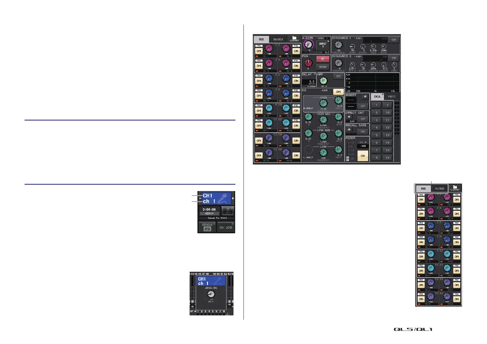
SELECTED CHANNEL VIEW screen
SEND field
In this field, you can view the send level and pre/post from the channel
to each MIX/MATRIX bus. You can also switch the on/off status of the
send signals. The view and the function of the knobs and buttons in
the SEND field vary depending on whether a pair of bus channels
(odd-numbered and even-numbered) are comprised of two mono
channels or a stereo channel.
1 Tabs
Enable you to select a group of 16 output bus channels to be
displayed in the SEND field.
• MIX tab .................................. displays MIX buses 1–16.
• MATRIX tab ........................... displays MATRIX buses 1–8.
STEP
1. Press the Bank Select keys in the Fader Bank section to select the bank that includes
the channel you want to operate.
2. Use a [SEL] key in the top panel channel strip section or the master section, to select
the channel to control.
3. If the SELECTED CHANNEL VIEW screen is not displayed, press one of the knobs in
the SELECTED CHANNEL section.
4. Use the knobs and the buttons in the screen to edit the parameters of the selected
channel.
Channel number
Channel name
1

 Loading...


