Input channels
Reference Manual
29
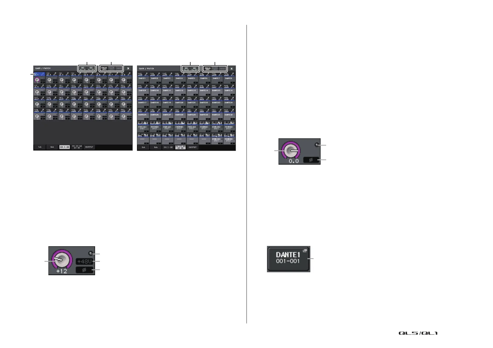
GAIN/PATCH window
(1–32, 33–64/ST IN (QL5), ST IN (QL1))
This window displays the head amp settings of the corresponding input channels. Here you
can also use the [TOUCH AND TURN] knob to adjust the selected head amp gain.
1 Parameter select buttons
Switch parameters to view in the window.
• ANALOG GAIN...................... Analog gain
• DIGITAL GAIN ....................... Digital gain
• PATCH ................................... Patch selection
2 GC ALL ON/GC ALL OFF buttons
Switch Gain Compensation on or off for all input channels simultaneously.
3 Channel select button
Selects the channel. You can select multiple channels simultaneously.
If you press the ANALOG GAIN parameter select button:
1
GAIN knob
Indicates the analog gain setting for each channel. Press the knob to select a channel,
and then control the gain value using the [TOUCH AND TURN] knob. If the Gain
Compensation function is turned on, an indicator will appear, showing the position of
the analog gain when the function is turned on.
2 OVER indicator
Lights when a signal at the input port or from the rack output exceeds the full scale level.
This indicator is available only if an input channel is selected.
3 +48V indicator
Indicates the +48V on/off status for each channel.
4 Ø (Phase) indicator
Indicates the phase setting for each channel.
NOTE
If the input channel is patched to a slot for which the connection to the head amp is not
recognized, the knob
1 will be replaced with the slot/port number of the patch destination.
3 will not be displayed.
If the input channel is patched to a rack, the knob
1 will be replaced with the port ID of the rack.
If nothing is patched to the input channel, the knob
1 will be replaced with a dotted line
“----”.
If you press the DIGITAL GAIN parameter select button:
1
GAIN knob
Indicates the digital gain setting for each channel. Press the knob to select a channel,
and then control the gain value using the [TOUCH AND TURN] knob.
2 OVER indicator
Lights when a signal at the input port or from the rack output exceeds the full scale level.
This indicator is available only if an input channel is selected.
3 Ø (Phase) indicator
Indicates the phase setting for each channel.
If you press the PATCH parameter select button:
1
PATCH button
Press this button to open the PORT SELECT window, in which you can select an input
port to patch to the channel.
1
3
2
4
1

 Loading...


