Input channels
Reference Manual
36
9 SEND LEVEL knob
Indicates the level of signals sent to the selected send destination. You can use the
[TOUCH AND TURN] knob to control the level.
If the send destination is set to FIXED, only a gray circle will appear.
Using the faders (SENDS ON FADER mode)
You can use the faders on the top panel to adjust signals that are sent from all input channels
to a specific MIX/MATRIX bus.
NOTE
• Press the SENDS ON FADER button to switch to SENDS ON FADER mode.
The faders in the Channel Strip section and Master section will move to the send levels of the
signals that are routed from each channel to the currently-selected MIX/MATRIX bus. The [ON]
keys will also change to the SEND ON status.
• If you press the currently-selected MIX/MATRIX bus select button again, cue monitoring will be
turned on for the related MIX/MATRIX channel. This method is convenient if you want to monitor
the signal that is being sent to the selected MIX/MATRIX bus.
• You can assign the SENDS ON FADER function to a USER DEFINED key. This lets you quickly
switch to SENDS ON FADER mode for a specific MIX/MATRIX bus, and quickly switch back
again.
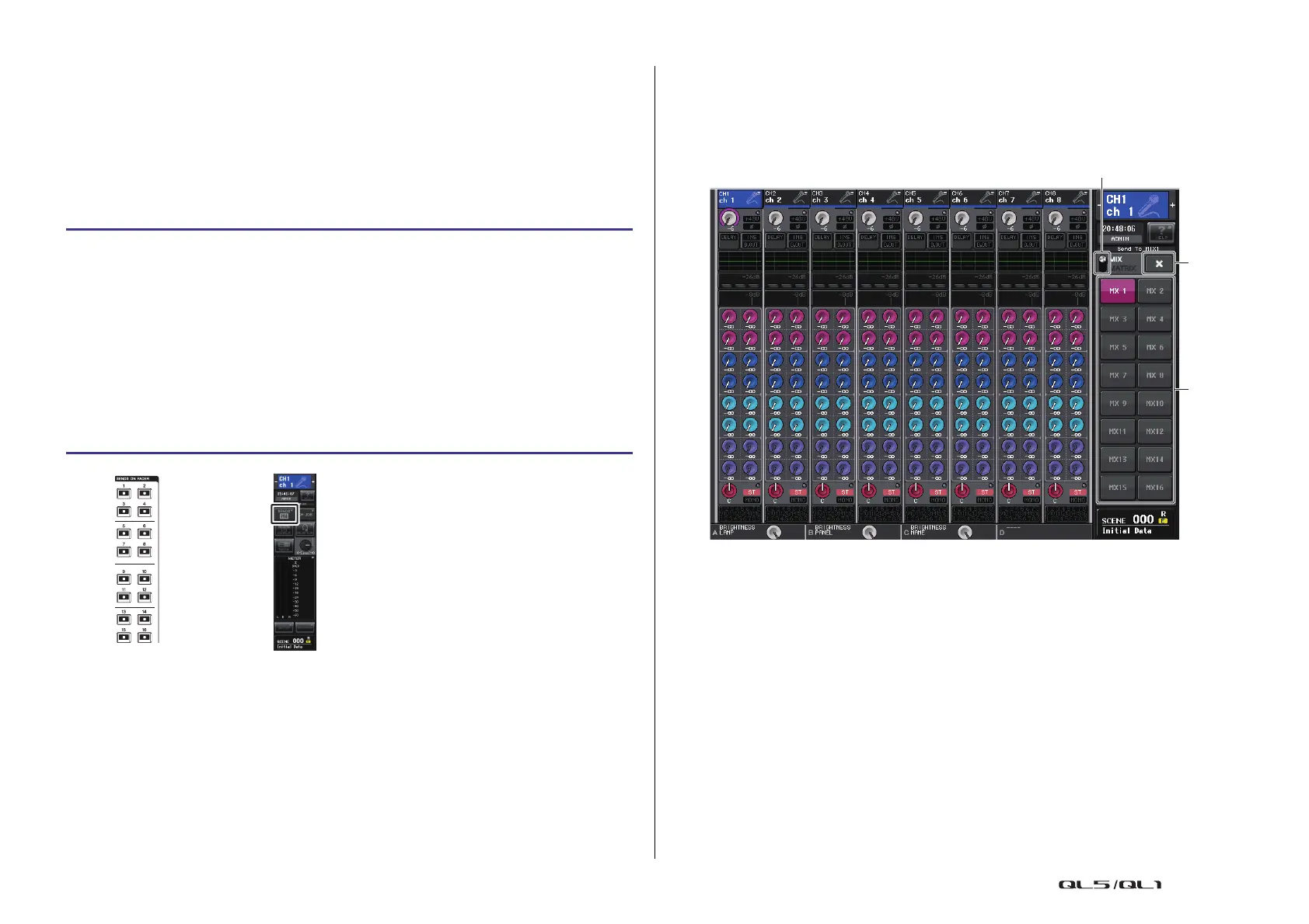
SENDS ON FADER mode
1 MIX/MATRIX select button
Use the MIX/MATRIX select button to switch between MIX/MATRIX for the bus
displayed in the Function Access Area.
2 MIX/MATRIX bus select buttons
Select the buses that will be controlled by the faders.
3 Close button
Closes the SENDS ON FADER mode.
STEP
1. Assign an output port to each MIX/MATRIX bus to which you want to send signals,
and connect your monitor system, external effects, or other device to the
corresponding output port.
2. In the Function Access Area, press the SENDS ON FADER button, or press the key
that is currently lit in the SENDS ON FADER section.
3. Use the MIX/MATRIX select buttons in the Function Access Area to switch between
MIX/MATRIX.
4. Use the MIX/MATRIX bus select buttons in the Function Access Area, or the key in
the SENDS ON FADER section to select the send-destination MIX/MATRIX bus.
5. Use the faders in the Channel Strip section on the top panel to adjust the send level
of signals routed from the input channels to the selected MIX/MATRIX bus.
SENDS ON FADER
section
Function
access area

 Loading...


