6-9
6
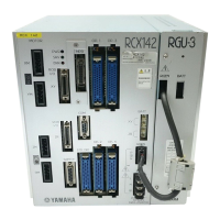
Parallel I/O interface
1. Standard I/O interface overview
1.7 Dedicated output signal description
1. DO01a CPU_OK output: contact A (normally open)
This is always on during normal controller operation.
In the following cases this output turns off and CPU operation stops.
• Serious malfunction
•When the power supply voltage has dropped to lower than the specified value.
Normal operation cannot resume if this signal is turned off once, without turning the
power supply on again.
2. DO01b CPU_OK output: contact B (normally closed)
This is a complementary (inverted) logic output of the CPU_OK (A contact).
3. DO02a Servo ON output: contact A (normally open)
This output is on when the motor power supply inside the controller is on. However
this signal turns off when a serious malfunction occurs or the emergency stop input
contacts are open. After the emergency stop input contacts close, when the servo turns
on in “UTILITY” mode or when the servo ON input (DI01) of the I/O interface are
turned on, then DO02a turns on at the same time.
The servo will not turn on if a serious malfunction occurs or the emergency stop input
contacts are open.
4. DO02b Servo ON output: contact B (normally closed)
This is a complementary (inverted) logic output of the servo ON (A contact) signal.
5. DO03a Alarm output: contact A (normally open)
This output turns on in the following cases.
(1) When contacts on the emergency stop switch open.
(2) When a driver unit detects a serious malfunction such as an overload.
(However does not include abnormalities from when the power is turned on.)
(3) When the host CPU has stopped due to a major abnormality or other causes.
(4) When battery voltage for retaining the memory is low or the battery is
disconnected.
However, even if an alarm is turned on due to a low battery, this does not
affect other conditions or execution of programs.
The ALARM LED on the controller monitor panel lights up simultaneously when an
alarm is triggered.
The alarm can be turned under the following conditions for each of the above cases.
In case (1)
After the emergency stop switch contacts have been closed, alarm turns off when
the emergency stop flag is canceled in “UTILITY” mode or the servo ON input
(DI01) of the I/O interface is turned on.
(This alarm can also be cancelled after the power is turned on again.)
In case (2)
Alarm turns off when the emergency stop flag is cancelled in “UTILITY” mode.
However, the alarm condition is maintained while the driver unit still has power so
the power must be turned off and then on again in order to turn on the servos and
restart the program.
 Loading...